guod
Well-Known Member
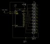
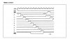
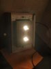
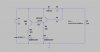
with current flows throu the fan we see a voltage drop over D1+R2, just enough to open Transistor Q1. this will fire up Led D2. (green).
the base of Q4 has now nearly the voltage of Vb, so this transistor is closed.
if the fan failed, no current flow, there is no voltage over D1+R2 so Q1 is closed.
now we have a current flow from the base of Q4 over R5+R4 and the green led.
Q4 is now open and the led D3 (red) will fire up
R2 needs some fine tuning,
zip file contains the .ASC file for Ltspice.
Attachments
-
631 bytes Views: 2