I'm looking at setting up a second tent and to save money I would like to run both light systems off the same ballast. How would I provide power to one light for 12h and then shift power to the other light for the next 12h and repeat? I'm assuming there exists some switcher but I've never seen one. Also would this cause earlier failure of a ballast, having it run continuously for months at a time? Thanks
One ballast to two alternating lights?
- Thread starter drnkrssn
- Start date
robert 14617
Well-Known Member
the ballast would have to shut down between switching, it could be done with three timers
you dont want to use a common timer after the ballast as they are not rated for the voltage.
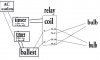
a dpdt relay will allow you to come off the ballast to the common terminals of the relay.tie 1 lamp into the N.O. terminals of the relay, the other into the N.C. terminals. energise the relay with a timer set for 12/12. when the relay is energized,the power will go to the lamp that is on the N.O. terminals.when the timer is off, power will go to the lamp on the N.C. terminals.another timer to power the ballast will be set to 23hr on 1 off to give the ballast time to cool.
a dpdt relay will allow you to come off the ballast to the common terminals of the relay.tie 1 lamp into the N.O. terminals of the relay, the other into the N.C. terminals. energise the relay with a timer set for 12/12. when the relay is energized,the power will go to the lamp that is on the N.O. terminals.when the timer is off, power will go to the lamp on the N.C. terminals.another timer to power the ballast will be set to 23hr on 1 off to give the ballast time to cool.
here is a crappy picture but I hope you get the idea
make sure the relay you use is able to handle switching 600 volts
something like this
http://www.grainger.com/Grainger/items/5X847
make sure the relay you use is able to handle switching 600 volts
something like this
http://www.grainger.com/Grainger/items/5X847
Attachments
-
 53 KB Views: 26
robert 14617
Well-Known Member
Why has my timer switch failed and what should I do?

Why has my timer switch failed and what should I do?
Contributed by: skunkaroo
Images archived
Editors safety note:
Skunkaroo's instructions below, failed to include a common ground.
It would be much safer to use three conductor cord so that a common ground could be incorporated into this project. Tie all the grounds together using either a four post terminal block instead of the three post block skunkaroo used below, or else tie all the grounds together using a large wire nut. It would also be benifical to tie this to a dedicated ground close to the grow, this can be as simple as a piece of pipe or ground rod driven in the earth with a piece of #8 tied to it.
Normal household timers are not designed or rated to deal with the inductive power load used by horticultural lighting. There are 2 ways around this, you could go to your local Hydro shop and buy a contactor all built and ready to go along with a hefty price tag. Or you can get yourself a suitable change over Contact Relay switch, this will only set you back a few $$ ££. A contact relay switch is required so that the timer turns on the contactor which then turns the light on.
Almost all new growers will experience this failure. The reason for this is the contacts in these timers are not sufficient for the job. Household timers are rated for a RESISTIVE load, ballasts present an INDUCTIVE load, (a very large surge at switch on) this fuses the timer contacts together = Timer failure.
What is a relay switch?
An electro mechanically operated switch.
What follows?
Complete instructions (including photos) on wiring a contact relay switch to replace your timer contacts.
What parts are needed and where can I buy them?
The following parts can be purchased at any good online electrical store ie maplin.co.uk rswww.com
In my case I run 1 x 400w HPS, I know the INDUCTIVE load is 3.15 amps at switch on. Ask the manufactures of your light for this info. I am also running 5 x PC fans and a 1 x PC power supply unit. I have chosen a 240 volt, 10 amp contact relay switch from maplin code JG60 & JG54 this particular Relay switch has screw-terminals for easy wiring, and a push fit, easy mount base.
You will also need a 3 way terminal block, 2 x 3 pin mains plugs, 1 x 3 pin female mains socket, 1.5 meter of 2 core mains wire, sharp wire cutters/blade, an electrical screwdriver, and a cross head screwdriver.

Wiring a relay switch.
Note: mains voltage can kill you! So please exercise caution when wiring electronics of any kind!
1. Cut your 2-core wire into 4 measures the same length. Now pre-pair the wire ends, cut 2” from the outer sheath, then cut 1 cm off the inner sheath to expose wire. *Optional - solder all wire ends*
2. Fit mains plugs to 2 of the 4 pieces of wire, and then 1 of the remaining pieces of wire to the female mains socket.

3. Select one of the pieces of cable terminated with a mains plug, and connect to the relay base as follows: - Connect the live wire (Brown) to terminal 7 on the relay base. Connect the Neutral wire (Blue) to terminal 2 on the relay base. These connections are used to energise the relay coil. Now label the mains plug “Timer” (Plug 1).

4. Select the second piece of cable terminated with a mains plug, and connect to the terminal block as follows: - Connect the live wire (Brown) to terminal 1 on the terminal block (see diagram for terminal block numbering sequence). Connect the Neutral wire (Blue) to terminal 3 on the terminal block (see diagram). These connections are used to operate the grow room light (via the relay contacts). Now label the mains plug “Power” (Plug 2).
5. Select the third piece of cable terminated with a female mains socket, and connect to the terminal block as follows: - Connect the live wire (Brown) to terminal 2 on the terminal block. Connect the neutral wire (Blue) to terminal 3 on the terminal block.
6. Select the final piece of wire and proceed as follows: -Connect one end of the Brown wire to terminal 1 on the terminal block, connect the other end of this wire to terminal 8 on the relay base. Connect one end of the Blue wire to terminal 2 on the terminal block, connect the other end of this wire to terminal 6 on the relay base. Note: under operating conditions both of these wires become live.


7. Now take the relay unit and plug into relay base. (Plug 1) plugs into the timer. (Plug 2) plugs into a separate power socket. The female mains socket will supply power to your grow room lights.

Principle of operation.
When the timer switches on it will provide power to the relay coil. This in turn closes the relay contacts and bridges the terminals 8 & 6 on the relay unit thus providing power to female mains socket.
Total cost = £10. Time taken = 30min. Total saving = £25-30.
Added on: Tuesday, May 1, 2007 Viewed: 1909 times
Why has my timer switch failed and what should I do?
Contributed by: skunkaroo
Images archived
Editors safety note:
Skunkaroo's instructions below, failed to include a common ground.
It would be much safer to use three conductor cord so that a common ground could be incorporated into this project. Tie all the grounds together using either a four post terminal block instead of the three post block skunkaroo used below, or else tie all the grounds together using a large wire nut. It would also be benifical to tie this to a dedicated ground close to the grow, this can be as simple as a piece of pipe or ground rod driven in the earth with a piece of #8 tied to it.
Normal household timers are not designed or rated to deal with the inductive power load used by horticultural lighting. There are 2 ways around this, you could go to your local Hydro shop and buy a contactor all built and ready to go along with a hefty price tag. Or you can get yourself a suitable change over Contact Relay switch, this will only set you back a few $$ ££. A contact relay switch is required so that the timer turns on the contactor which then turns the light on.
Almost all new growers will experience this failure. The reason for this is the contacts in these timers are not sufficient for the job. Household timers are rated for a RESISTIVE load, ballasts present an INDUCTIVE load, (a very large surge at switch on) this fuses the timer contacts together = Timer failure.
What is a relay switch?
An electro mechanically operated switch.
What follows?
Complete instructions (including photos) on wiring a contact relay switch to replace your timer contacts.
What parts are needed and where can I buy them?
The following parts can be purchased at any good online electrical store ie maplin.co.uk rswww.com
In my case I run 1 x 400w HPS, I know the INDUCTIVE load is 3.15 amps at switch on. Ask the manufactures of your light for this info. I am also running 5 x PC fans and a 1 x PC power supply unit. I have chosen a 240 volt, 10 amp contact relay switch from maplin code JG60 & JG54 this particular Relay switch has screw-terminals for easy wiring, and a push fit, easy mount base.
You will also need a 3 way terminal block, 2 x 3 pin mains plugs, 1 x 3 pin female mains socket, 1.5 meter of 2 core mains wire, sharp wire cutters/blade, an electrical screwdriver, and a cross head screwdriver.
Wiring a relay switch.
Note: mains voltage can kill you! So please exercise caution when wiring electronics of any kind!
1. Cut your 2-core wire into 4 measures the same length. Now pre-pair the wire ends, cut 2” from the outer sheath, then cut 1 cm off the inner sheath to expose wire. *Optional - solder all wire ends*
2. Fit mains plugs to 2 of the 4 pieces of wire, and then 1 of the remaining pieces of wire to the female mains socket.
3. Select one of the pieces of cable terminated with a mains plug, and connect to the relay base as follows: - Connect the live wire (Brown) to terminal 7 on the relay base. Connect the Neutral wire (Blue) to terminal 2 on the relay base. These connections are used to energise the relay coil. Now label the mains plug “Timer” (Plug 1).
4. Select the second piece of cable terminated with a mains plug, and connect to the terminal block as follows: - Connect the live wire (Brown) to terminal 1 on the terminal block (see diagram for terminal block numbering sequence). Connect the Neutral wire (Blue) to terminal 3 on the terminal block (see diagram). These connections are used to operate the grow room light (via the relay contacts). Now label the mains plug “Power” (Plug 2).
5. Select the third piece of cable terminated with a female mains socket, and connect to the terminal block as follows: - Connect the live wire (Brown) to terminal 2 on the terminal block. Connect the neutral wire (Blue) to terminal 3 on the terminal block.
6. Select the final piece of wire and proceed as follows: -Connect one end of the Brown wire to terminal 1 on the terminal block, connect the other end of this wire to terminal 8 on the relay base. Connect one end of the Blue wire to terminal 2 on the terminal block, connect the other end of this wire to terminal 6 on the relay base. Note: under operating conditions both of these wires become live.
7. Now take the relay unit and plug into relay base. (Plug 1) plugs into the timer. (Plug 2) plugs into a separate power socket. The female mains socket will supply power to your grow room lights.
Principle of operation.
When the timer switches on it will provide power to the relay coil. This in turn closes the relay contacts and bridges the terminals 8 & 6 on the relay unit thus providing power to female mains socket.
Total cost = £10. Time taken = 30min. Total saving = £25-30.
Added on: Tuesday, May 1, 2007 Viewed: 1909 times
hiroshima
Active Member
Read all of this page so you have a better understanding of relaysNormally-open (NO) contacts connect the circuit when the relay is activated; the circuit is disconnected when the relay is inactive. It is also called a Form A contact or "make" contact.
Normally-closed (NC) contacts disconnect the circuit when the relay is activated; the circuit is connected when the relay is inactive. It is also called a Form B contact or "break" contact.
Change-over (CO), or double-throw (DT), contacts control two circuits: one normally-open contact and one normally-closed contact with a common terminal. It is also called a Form C contact or "transfer" contact ("break before make"). If this type of contact utilizes a "make before break" functionality, then it is called a Form D contact.
http://en.wikipedia.org/wiki/Relay
correctGreat that makes sense. The cord to the light is cut and hardwired to terminals?
normally open & normally closedWhat do N.O. N.C. stand for?
with AC wiring, it is not + & - but hot and neutral. make sure the hot to each lamp goes to the hot side of the relayDo +/- wire positioning matter, does the ground get a terminal?
a relay is basicly a switch controlled by power.when not powered,each common will be connected to one N.C. terminal,when powered, the switch will flip and the common will connect to the N.O. terminal. a DPDT (double pole,double throw)relay is 2 switches.common 1 goes to N.O1 or N.C.1 & common2 goes to N.O2 & N.C.2(depending on if powered)
just connect all the grounds together
only that it is running all the timeIs there a downside to using a ballast in this way? Thanks
as a late thought, it would be better for the relay if power was off to the ballast when the relay flips so 2 off times might be better- each 1/2 hr with the relay flipping during the off time.
the key to longer ballast life is a cool down period every day so two 1/2 hr times off should do it, the trick will be to get the 2 timers to coinside w/ each other so the ballast is off when the relay timer flips the relay.
nice post. i will add that this was done over in the UK so it talks about blue and brown wires for hot & neutral but idea is the sameWhy has my timer switch failed and what should I do?
the relay they use is a DPST(double pole,single throw) so it will have 2 commons & 2 N.O. terminals but no N.C. terminals
LUDACRIS
New Member
Why has my timer switch failed and what should I do?
Why has my timer switch failed and what should I do?
Contributed by: skunkaroo
Images archived
Editors safety note:
Skunkaroo's instructions below, failed to include a common ground.
It would be much safer to use three conductor cord so that a common ground could be incorporated into this project. Tie all the grounds together using either a four post terminal block instead of the three post block skunkaroo used below, or else tie all the grounds together using a large wire nut. It would also be benifical to tie this to a dedicated ground close to the grow, this can be as simple as a piece of pipe or ground rod driven in the earth with a piece of #8 tied to it.
Normal household timers are not designed or rated to deal with the inductive power load used by horticultural lighting. There are 2 ways around this, you could go to your local Hydro shop and buy a contactor all built and ready to go along with a hefty price tag. Or you can get yourself a suitable change over Contact Relay switch, this will only set you back a few $$ ££. A contact relay switch is required so that the timer turns on the contactor which then turns the light on.
Almost all new growers will experience this failure. The reason for this is the contacts in these timers are not sufficient for the job. Household timers are rated for a RESISTIVE load, ballasts present an INDUCTIVE load, (a very large surge at switch on) this fuses the timer contacts together = Timer failure.
What is a relay switch?
An electro mechanically operated switch.
What follows?
Complete instructions (including photos) on wiring a contact relay switch to replace your timer contacts.
What parts are needed and where can I buy them?
The following parts can be purchased at any good online electrical store ie maplin.co.uk rswww.com
In my case I run 1 x 400w HPS, I know the INDUCTIVE load is 3.15 amps at switch on. Ask the manufactures of your light for this info. I am also running 5 x PC fans and a 1 x PC power supply unit. I have chosen a 240 volt, 10 amp contact relay switch from maplin code JG60 & JG54 this particular Relay switch has screw-terminals for easy wiring, and a push fit, easy mount base.
You will also need a 3 way terminal block, 2 x 3 pin mains plugs, 1 x 3 pin female mains socket, 1.5 meter of 2 core mains wire, sharp wire cutters/blade, an electrical screwdriver, and a cross head screwdriver.
Wiring a relay switch.
Note: mains voltage can kill you! So please exercise caution when wiring electronics of any kind!
1. Cut your 2-core wire into 4 measures the same length. Now pre-pair the wire ends, cut 2 from the outer sheath, then cut 1 cm off the inner sheath to expose wire. *Optional - solder all wire ends*
2. Fit mains plugs to 2 of the 4 pieces of wire, and then 1 of the remaining pieces of wire to the female mains socket.
3. Select one of the pieces of cable terminated with a mains plug, and connect to the relay base as follows: - Connect the live wire (Brown) to terminal 7 on the relay base. Connect the Neutral wire (Blue) to terminal 2 on the relay base. These connections are used to energise the relay coil. Now label the mains plug Timer (Plug 1).
4. Select the second piece of cable terminated with a mains plug, and connect to the terminal block as follows: - Connect the live wire (Brown) to terminal 1 on the terminal block (see diagram for terminal block numbering sequence). Connect the Neutral wire (Blue) to terminal 3 on the terminal block (see diagram). These connections are used to operate the grow room light (via the relay contacts). Now label the mains plug Power (Plug 2).
5. Select the third piece of cable terminated with a female mains socket, and connect to the terminal block as follows: - Connect the live wire (Brown) to terminal 2 on the terminal block. Connect the neutral wire (Blue) to terminal 3 on the terminal block.
6. Select the final piece of wire and proceed as follows: -Connect one end of the Brown wire to terminal 1 on the terminal block, connect the other end of this wire to terminal 8 on the relay base. Connect one end of the Blue wire to terminal 2 on the terminal block, connect the other end of this wire to terminal 6 on the relay base. Note: under operating conditions both of these wires become live.
7. Now take the relay unit and plug into relay base. (Plug 1) plugs into the timer. (Plug 2) plugs into a separate power socket. The female mains socket will supply power to your grow room lights.
Principle of operation.
When the timer switches on it will provide power to the relay coil. This in turn closes the relay contacts and bridges the terminals 8 & 6 on the relay unit thus providing power to female mains socket.
Total cost = £10. Time taken = 30min. Total saving = £25-30.
Added on: Tuesday, May 1, 2007 Viewed: 1909 times
exellent info rob
 .
.(saved).
CHRIS.