MeanWell LED Drivers: 3 in 1 Dimming Function.

Timothypaul26

Well-Known Member
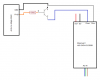
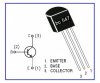
I am trying to make sense of the PWM setup. I am using a L7810CV, as SDS instructed along with a BC547BTA transistor and a 4.7k ohm Rb resistor. This was the only way that I could actually see a
movement in the voltage from ~0 to ~9.5V using the arduino fade example code. I am somewhat new to all of this, I'll just put that out there. But once I introduce the HLG-24H-C1050B it seems to latch at ~10V. Maybe I'm missing something, but with the other examples I was not able to get a voltage change. So if anyone with and advice can help out, I would be grateful.


guod

Well-Known Member
you are right, edit my above post
Q.: what happend if you disconnect the base. - normally the Led turns off.
Q.: what happend if you connected the base (resistor is needed) to 5V - normally the led turns on.
if both cases are true in your build then there is a problem with the Arduino... sketch or wrong pin..
 

Timothypaul26

Well-Known Member
Disconnect the base in CBE orientation I get a few mV, 0-350mV. Seems like its still getting something from the PWM pin a little bit. In the EBC orientation steady 3.173V. I am not sure I understand your 2nd Q, I have the base and the 5V PWM pin9 seperated, and then joined by the 4.7K Rb resistor.
Code:
/*
Fade
This example shows how to fade an LED on pin 9
using the analogWrite() function.
This example code is in the public domain.
*/

int led = 9;           // the pin that the LED is attached to
int brightness = 0;    // how bright the LED is
int fadeAmount = 5;    // how many points to fade the LED by

// the setup routine runs once when you press reset:
void setup()  {
  // declare pin 9 to be an output:
  pinMode(led, OUTPUT);
}

// the loop routine runs over and over again forever:
void loop()  {
  // set the brightness of pin 9:
  analogWrite(led, brightness);   

  // change the brightness for next time through the loop:
  brightness = brightness + fadeAmount;

  // reverse the direction of the fading at the ends of the fade:
  if (brightness == 0 || brightness == 255) {
    fadeAmount = -fadeAmount ;
  }    
  // wait for 30 milliseconds to see the dimming effect   
  delay(30);                           
}
 

CrazyKappa

Well-Known Member
Thank for all the work everyone has put into this, just wired up my 9 CXB 3590 light running @1050mA. Have two drivers, so used a 50k pot, and 5 1k resistors wired in series, could not find a 5k resistor locally. I bought the resistors before i understood what they were actually doing, or i would have just went with the 5.6k, but they seem to work fine.

I cant find my multi-meter, will have to borrow one, but a kilo-a-watt meter is saying 360w full power, around 40w all the way dimmed. I do plan on buying a actual controller in the future, so i can get sunset/sunrise mode, but for now, this will do.

The only thing that i do not understand is, people have mentioned that the actual CXBs will run a bit higher then 100%. People have suggested a toggle switch on the DIM- led, before the resistors, so that you get the lights full potential. Yet still, other people have said, so long as your resistance reaches 100k for a single driver, (50k for my setup) the driver will perform at its full potential. So what is the truth? Should i install a switch, or should i just verify that between my pot, and resistors, i am getting 50k of resistance? I don't really feel like redoing my system for nothing, but if i can gain 5+% in output, ill install the damn switch.

Also do they make a dimming controller that has sunrise/sunset, as well as the ability to dim the lights if my room reaches a certain temperature? I know they make HID controllers that shut the lights off if it gets too hot, but i would rather have that be a dimming function.

Thanks for everything guys!
 
Last edited:

Timothypaul26

Well-Known Member
@KrazyKappa it is my understanding that by forcing the Dim+ to Dim- circuit to open, will provide full 100%, or even slightly higher, this can also be achieved by as you stated a 100K resistance. You can use a switch or a relay to get the results you're looking for.

As for my issue that I've been working on I plugged in my LED driver because I was assuming that it was latching to 10V, but my multimeter reads 10V coming from the Dim leads. Is this normal?and if so, why do I even need the 10V regulator?
 
Last edited:

Timothypaul26

Well-Known Member
I figured out my issue!! The build I posted works perfectly until I add my HLG to the circuit. It is adding voltage and there is nowhere for the extra voltage to go, so it just raises the entire system voltage to match. I added a resistor between Dim+ and Dim- and it works!! So to figure out what resistor would work best, I used a 50K pot and once I got it down ~1V and as high as ~9.5V it was around 10.3K ohms. I added my HLG and perfection!! Only issue I was having, is that I actually want to control 2 HLG's, so ended up with a 4.7K as 10K was not longer enough drain for the 2 HLG's.
 

Timothypaul26

Well-Known Member
Also want to add that I am still using the code posted above, and fade to 0 gives me ~1V, this is great since you don't want to try to dim below 11%. It's not good for the driver.
 

Timothypaul26

Well-Known Member
I had a long conversation, learning session with an electronics guru at work today. I didn't understand the whole PWM circuit as a whole. I now have a much better understanding of it. The circuit that I built, although working, isn't really correct. He agreed with me that if you already have 10V in the LED driver Dim+, you don't need to add the 12V to 10V regulator. He suggested a circuit that would be more efficient. I will try it out and post it, if it proves out.
 

Timothypaul26

Well-Known Member
Here is the proven method, I get the same voltage as an open circuit. I decided to use a 2N3904, as it seemed to work the best. I picked it up in a 15 pack at radio shack, came with 5x 2N2222, 5x 2N3904, and 5x 2N4401. I also had some BC547BTAs, but the 2N3904 seemed to be less prone to leakage. You will need to be careful on how you set your dim adjustment though, as you will go all the way to 0V at 255, I think for my tests I just kept it at 222 in the fade code 0 being 10V and 255 being 0V.
 

Attachments

looshis

New Member
I am trying to dim a few LED strips using a single HLG-120H-12B and a 100k ohm pot, with a 10k resistor attached. Right now, I have it wired as shown in the attached image.

The potentiometer does not seem to affect the power output until it is turned about 90% of the way, at which point it will decrease the power slightly. Does anybody have any idea what might be causing this? I have tried three different pots, and have gotten the same result every time.

Thanks in advance.
 

Attachments

Timothypaul26

Well-Known Member
I am trying to dim a few LED strips using a single HLG-120H-12B and a 100k ohm pot, with a 10k resistor attached. Right now, I have it wired as shown in the attached image.

The potentiometer does not seem to affect the power output until it is turned about 90% of the way, at which point it will decrease the power slightly. Does anybody have any idea what might be causing this? I have tried three different pots, and have gotten the same result every time.

Thanks in advance.
Do you have a multimeter? You can verify that your pot is working,
making sure it goes from 0ohms to100k ohms. Your picture looks correct.
 

looshis

New Member
Do you have a multimeter? You can verify that your pot is working,
making sure it goes from 0ohms to100k ohms. Your picture looks correct.
Yes - the multimeter indicates that the pot goes from 0.0 ohms to ~97k ohms.

Its kind of strange. If the pot is a clock face where 6:31 is 100k resistance and, turning the knob clockwise, 6:29 is zero resistance, my pots seem to only be working between approx. 6:31 and 6:45. If I start with the pot at 6:31 the LEDs are appx 90% brightness. As I turn clockwise, they get slightly brighter until I get to 6:45, at which point they're at 100% brightness, and that's where they stay when I keep turning the knob clockwise from 6:45 all the way around to 6:29.

Also, it seems that when the pot is turned anywhere between 0-90% there is 10mA current flowing between the dim wires. When it is turned past 90%, it will start to drop, and will continue to drop to about 3mA at 100%.
 
Last edited:

Timothypaul26

Well-Known Member
Not sure what you have going on with that pot, but it sounds faulty. If you have another one available, I'd try it out. Even a 50k pot will give you a 60% sweep with your 10k added in. As for turning direction for dimming, you can swap legs on the pot to give you dim cw, bright ccw, or swap legs for dim ccw and bright cw
 

looshis

New Member
Not sure what you have going on with that pot, but it sounds faulty. If you have another one available, I'd try it out. Even a 50k pot will give you a 60% sweep with your 10k added in. As for turning direction for dimming, you can swap legs on the pot to give you dim cw, bright ccw, or swap legs for dim ccw and bright cw
Okay, I've tested five different pots and have gotten the same result every time. I'm wondering whether the LEDs I'm using don't draw enough power to be affected by the dimming. According to the spec sheet, my LED modules draw 0.96w each @12 volts. I have 100 modules hooked up, which means it would draw 8 amps on full brightness.

If I am reading the specs right (see, http://www.meanwell.com/mw_search/HLG-120H/HLG-120H-spec.pdf ) the HLG-120H-12B can only be adjusted between 5 - 10A. Am I reading that correctly? If that is true, then it makes sense that the LEDs are only dimming toward the end of the pot, when the resistance is low enough to start taking 8 amps down toward 5 amps. And if the LEDs drew less than 5 amps at full brightness, the dimmer really wouldn't work at all. Or am I thinking about this incorrectly?

And thanks for your help, Timothypaul26!
 

Timothypaul26

Well-Known Member
Even with no led'so hooked up, you should be getting a 0-10v swing. You should be measuring voltage between dim+ and dim-. Try hooking up and testing without the 10k resistor along with your meter so you can verify your voltage swing, and can be sure not to go below 1v that way. Also, might want to double check that resistor is indeed 10k, and that you didn't accidentally read it wrong. I've done that a few times myself
 

VegasWinner

Well-Known Member
There is also a 5v to 10v converter on the same page for like $11 per channel. I also have found out 2 20k resisters on one leg turns 10v into 5v pwm signal too. Peace.
 
Top