Jade

Positivity

Well-Known Member
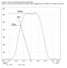
So if you wanted to harness all of the light with a reflector...

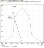
60* reflector will put all your light at 85% +, with less possible "wasted light".....?

Not that I think reflectors are necessary. But, it'd give you a more evenly distributed footprint. Instead of a range of 10% to 100%, you'd have a range of 85% to 100%.
 
Last edited:

churchhaze

Well-Known Member
Not only is the light at 60 degrees and beyond less than 50% the central axis, the light is also at a very low altitude to the plants (off the horizon). The light is coming in from a low angle. This could be a benefit assuming the entire canopy has 90 degree altitude light and 30 degree altitude (and lower) light sources on each side. It could also be disadvantage obviously.

A 60 degree reflector would make sense since it's hard to make use of such low altitude light (30 degrees and lower).
 

Positivity

Well-Known Member
I noticed that on the chart for my ledil reflector. I don't care for the strong peak in the middle as it probably contributes to light burn

I suppose ideally you'd want to use a collimater/tir type to collect the light and disperse it at a nice angle like 90* evenly. But then there's things like trapping a cobs heat under glass which can't be good for the lifespan and Tj
.
 

churchhaze

Well-Known Member
The efficiency of the reflectors only affects the small portion of light reflected (the negligible portion), while the lens attenuates the entire beam pattern.

I also meant 60 degrees as in 120 total degrees.
 

Positivity

Well-Known Member

"Up to now it was sufficient to use relatively cheap plastic materials for collimators and metal or plastics as reflector substrates. But the latest improvements in LEDs lead to lumen packages and energy densities that will exceed the specifications, mainly temperature characteristics, of the mentioned materials."

Good read..thanks
 

Positivity

Well-Known Member
lens
Viewing Angle (FWHM) 78°
Efficiency 93 %

reflector
Viewing Angle (FWHM) 71°
Efficiency 92 %

seems that the reflector has the same problem

My Tj temps seemed to be okay with the reflectors. Could be wrong though..no fried eggs yet..

Or if talking about efficiencies...I don't think that's a deal killer. The light shooting off at a wide angle isn't much better. Complicated subject, lots to consider. More than I can work out by thinking about it. I'm sure the optic companies are working at solutions that will hopefully suit us. In the meantime, with use, the reflectors work alright...:razz:....i tend to prefer them reflected but I do switch back and forth and observe as usual..
 
Last edited:

PSUAGRO.

Well-Known Member
I noticed that on the chart for my ledil reflector. I don't care for the strong peak in the middle as it probably contributes to light burn

I suppose ideally you'd want to use a collimater/tir type to collect the light and disperse it at a nice angle like 90* evenly. But then there's things like trapping a cobs heat under glass which can't be good for the lifespan and Tj
.
Yep^^^.......................heat difference on the innoled fixture was immediate and drastic with the secondary lens ON.
 

stardustsailor

Well-Known Member
Next step will be the preparation of the inner plate.
In that plate the heatsink attaches on bottom ,
whlile on top of the plate the two drivers are going to be placed ,
along with the fan and two support bars.

PB181828.JPG

With the two diagonal lines ,the center of the plate is found.
With that as reference point the fan opening is drawn
( Diameter same as of inner side of the 'ring' of fan's frame).
That circle has to be an opening.
The rectangle is the heatsink.

Few other openings have to be done .

8 x 3mm for the pcb spacers -attachment points of the two drivers
2 x 8mm for the wire silicone grommets .(the output wires of the CC drivers to COBs )
4 x 3 mm for the silicone anti-vibration fan mounting pins.
& of course 8x 4 mm for attaching the heatsink to the plate .

Two support bars -made of aluminium profile - will be attached to the plate ,
along the heat sink attachment screw rows ,one at each side.
PB181838.JPG
Those bars will be carrying all the weight load of the heatsink ( 1990 grs ) ,
transferring it to the steel made side walls .....
PB181835.JPG
....and from there to the also steel-made top lid ,from where the fixture is hanged .


And a rough -rough idea about the top/front -lloks of the fixture ...
PB181831.JPG


Cheers.
 
Last edited:

stardustsailor

Well-Known Member
Slow progression on that one ...

The inner plate and it's support bars ...
PB191839.JPG


Cutting with a ...drill ...
Remembered my father showing me this method ,about ... 30 years ago ..
PB191841.JPG :smile::smile::smile::smile::smile:....


At least the support bars are (almost...) ready .
They have holes running the sides of them ,so for the wiring to be tied up ,there..
PB191842.JPG


Cheers.
 

AquariusPanta

Well-Known Member
About 5 kilos ( ~ 10 pounds ,more or less ) ..
Thank you for the conversion :)

I wanna guess that my BlackStar V2 240W weights ~10 pounds or so, which I consider lightweight.

In comparison, your making much more out of your product's weight, which is evident with all your depicted gizmos and layouts.

How long will / did it take you to drill all those holes alone the perimeter of your circle on the aluminum slab there? I never thought about using a drill press to carve out a circle out of aluminum before but I can now see the challenge behind it. Your doing it though!
 

epicfail

Well-Known Member
Using a drill for cutting quite common with metal work by hand, rough it out with the drill and detail the rest with metal files... Old-school. I feel lucky I work with cnc routers and laser cutter, neither is good with steel but being able to cnc aluminum is unbelievably handy.
 
Top