Having an issue with my chiller not turning off.
- Thread starter Airwalker16
- Start date
dstroy
Well-Known Member
Its’ actual name is a continuity test, or maybe we’d measure the resistance, which is measured in Ohms. Regardless, I’ve never heard anyone in the industry I’m in refer to it as “ohming out”. Seems to be a bunch of diyers that call it that, not professionals. It’s too ambiguous to refer to it as what you called it, are you checking for resistance? Or just for continuity? don’t know because you said to “ohm it out”. See? So call it a continuity test if you are checking to see if the circuit is closed or open, or say to test the resistance if you need the resistance value which is useful troubleshooting info as well. I bet next you’ll try and tell me you have an omega symbol on your DMM and that’s why it’s called what you called it. It’s not.It’s not called “ohming out”, Try putting "OHMING OUT" in Google
Jypsy Dog
Well-Known Member
"ohming out" it's like the word douchebag, now you get it??Its’ actual name is a continuity test, or maybe we’d measure the resistance, which is measured in Ohms. Regardless, I’ve never heard anyone in the industry I’m in refer to it as “ohming out”. Seems to be a bunch of diyers that call it that, not professionals. It’s too ambiguous to refer to it as what you called it, are you checking for resistance? Or just for continuity? don’t know because you said to “ohm it out”. See? So call it a continuity test if you are checking to see if the circuit is closed or open, or say to test the resistance if you need the resistance value which is useful troubleshooting info as well. I bet next you’ll try and tell me you have an omega symbol on your DMM and that’s why it’s called what you called it. It’s not.
dstroy
Well-Known Member
lol"ohming out" it's like the word douchebag, now you get it??
Airwalker16
Well-Known Member
So would I just unsolder them from the pcb, open them, and check the coils manually? or is there a way to do it while still on pcb? same with the transistor and output pin? which piece on this pcb is the transistor? aND thanks so much for the strightforward answer. this is what I've been looking for.Yeah, no. If the temperature displayed on the unit is correct and you’ve verified the reading with a separate thermometer then it is not the temperature probe.
It’s not called “ohming out”, it’s called a continuity test, or sometimes ringing out, but ringing out is reserved for long cable runs usually, or that thing audio engineers do to prevent feedback. Checking for resistance is related to a continuity test.
Anyways, it’s easy enough to check if the relay is sticking on, all you do is check to see if the coil is deenergized when the set point has been reached, and you think the control signal should be low ie if the desired temp has been reached the coil for the relay should not be receiving power anymore. If it’s deenergized and the contacts are still closed then the relay is sticking closed. It is also a very easy replacement, and cheap if that’s the case. The other thing that could be wrong is that the little transistor, which is the “switch” for the relay might have failed, which is also easy to test for, or the resistor that pulls the gate (transistor gate) low could be bad.
Worst case scenario is that the output pin on the micro controller is malfunctioning. Also easy to check for if you follow the trace back from the gate on that transistor. Should be “low” when the compressor should be off.
Last edited:
Airwalker16
Well-Known Member
One thing I did actually find though, @dstroy , if you read this post on another site, someone who had a thread about an issue they were having with their chiller. An owner of this model said something that made me think twice about the thermostat actually being the issue. His username is Jolly Rancher and he states:
Ice probes are a joke.
If you want a non moving part(s) chiller using these (Peltier devices) they are not cheap.
http://www.customchill.com/cral300dp/
I have used Eco chillers and the "weak link" that I found is the nutrient solution (soup) reacts with the thermocouple and then the chiller won't shut off.
It won't "freeze up" and the plant loved the shit out of the oxygen rich soup.
I didn't appreciate the condensation pools underneath my plumbing.
Keep spare TC's to replace a bad one.
http://www.marijuanagrowing.com/showthread.php?22778-Reservoir-Chillers/page2
2nd Post of Page.
What do you think about this ?
Don't know what the freeze up part means exactly but I think he means the chiller coming to a complete stop like it's supposed to with just the power light on when it reachs the set temp.
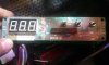
This is exactly what mine isn't doing. the external heater light comes on and the fan runs with warm air out the back and that temp just gets colder and colder. like the chiller knows it's too cold even, so that light comes on and the 2-prong outlet port on the back of the machine receives power for a submersible heater element cartridge to be plugged in and dangling in your fish tank. It's so weird weird, because when it WAS working a few weeks ago, it just shuts off or "freezes up" as this guy says when set temp is hit.
You can see the outlet in the back here detached from the base. the barrel fuse is housed right above it.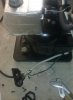
Ice probes are a joke.
If you want a non moving part(s) chiller using these (Peltier devices) they are not cheap.
http://www.customchill.com/cral300dp/
I have used Eco chillers and the "weak link" that I found is the nutrient solution (soup) reacts with the thermocouple and then the chiller won't shut off.
It won't "freeze up" and the plant loved the shit out of the oxygen rich soup.
I didn't appreciate the condensation pools underneath my plumbing.
Keep spare TC's to replace a bad one.
http://www.marijuanagrowing.com/showthread.php?22778-Reservoir-Chillers/page2
2nd Post of Page.
What do you think about this ?
Don't know what the freeze up part means exactly but I think he means the chiller coming to a complete stop like it's supposed to with just the power light on when it reachs the set temp.
This is exactly what mine isn't doing. the external heater light comes on and the fan runs with warm air out the back and that temp just gets colder and colder. like the chiller knows it's too cold even, so that light comes on and the 2-prong outlet port on the back of the machine receives power for a submersible heater element cartridge to be plugged in and dangling in your fish tank. It's so weird weird, because when it WAS working a few weeks ago, it just shuts off or "freezes up" as this guy says when set temp is hit.
You can see the outlet in the back here detached from the base. the barrel fuse is housed right above it.
Last edited:
Airwalker16
Well-Known Member
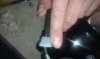
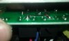
Well you can see in these pics that isnt the case.this is what your resistor will look like.
rkymtnman
Well-Known Member
not yet.Well you can see in these pics that isnt the case.View attachment 4039323
dstroy
Well-Known Member
That’s a diode, used to suppress the voltage spike that’s caused by the magnetic field collapse when power is removed from the coil. “Flyback diode”. There’s a power resistor over to the right of the transformer in the pictures “R1”.Well you can see in these pics that isnt the case.View attachment 4039323
You don’t have to unsolder anything to test the relays.
I read the post about the thermocouple, but again If you check the temp with a separate thermometer and both the chiller display and thermometer are the same temperature then the thermocouple is fine. Not sure what your thermocouple is made out of but it looks like an RTD, which are usually stainless steel probe bodies. You can remove the probe from the tank and look at the tip, it should be smooth and clean.
To see if the thermocouple is bad, just unplug the connector from the pcb and check the resistance of the thermocouple, it should not be open or zero.
dstroy
Well-Known Member
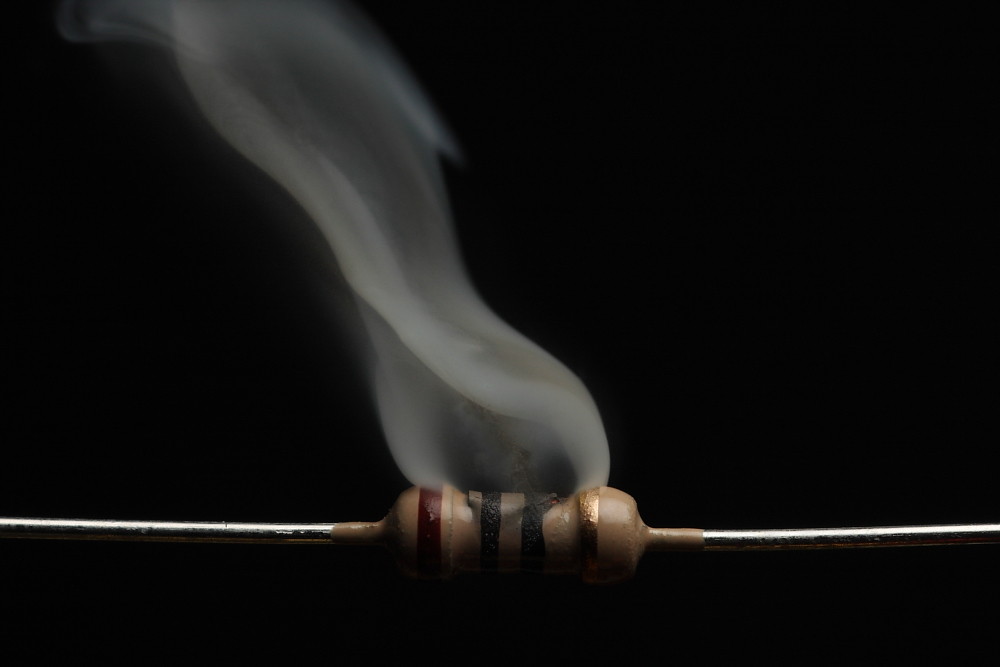
I believe that @rkymtnman was just trying to tell you that if there was a bad resistor, you would know because it’d be burnt, which is true especially for power resistors most of the time. You can check if it’s bad by looking up the value of the resistor. You do that by looking at the colored bands on it, which translates to resistance value, and tolerance (the amount +/-% of resistance which is considered nominal).
rkymtnman
Well-Known Member
also the old electronics joke that once you let the smoke out, things stop working.I believe that @rkymtnman was just trying to tell you that if there was a bad resistor, you would know because it’d be burnt, which is true especially for power resistors most of the time. You can check if it’s bad by looking up the value of the resistor. You do that by looking at the colored bands on it, which translates to resistance value, and tolerance (the amount +/-% of resistance which is considered nominal).
dstroy
Well-Known Member
Gotta keep that magic smoke in man, that’s what the pixies eat.also the old electronics joke that once you let the smoke out, things stop working.
Airwalker16
Well-Known Member
OH it's been examined already. looked just fine. if you create an account with that website, Jolly Rancher includes a pic of his and it looks really rough. mine looks great.That’s a diode, used to suppress the voltage spike that’s caused by the magnetic field collapse when power is removed from the coil. “Flyback diode”. There’s a power resistor over to the right of the transformer in the pictures “R1”.
You don’t have to unsolder anything to test the relays.
I read the post about the thermocouple, but again If you check the temp with a separate thermometer and both the chiller display and thermometer are the same temperature then the thermocouple is fine. Not sure what your thermocouple is made out of but it looks like an RTD, which are usually stainless steel probe bodies. You can remove the probe from the tank and look at the tip, it should be smooth and clean.
To see if the thermocouple is bad, just unplug the connector from the pcb and check the resistance of the thermocouple, it should not be open or zero.
Here's Jolly ranchers pic:
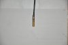
And here is mine:
Airwalker16
Well-Known Member
Ok. so can you reply to my other questions in that post?Gotta keep that magic smoke in man, that’s what the pixies eat.")
Airwalker16
Well-Known Member
This one^ and how do I test all of this without unsoldering anything ? I can take as many pics of whatever you need me to if you can help walk me through it. I know I could use a temp controller or a timer to just bypass all the troubles like I am now, but I really want this thing to function like it's supposed to, damn it!!!So would I just unsolder them from the pcb, open them, and check the coils manually? or is there a way to do it while still on pcb? same with the transistor and output pin? which piece on this pcb is the transistor? aND thanks so much for the strightforward answer. this is what I've been looking for.

Last edited:
Airwalker16
Well-Known Member
Also, I have looked into relays online and cannot find any with those exact markings on them. The top value of 10 amps-250v I can find but below that there are letters COS after 50hz that I can't seem to find on any of the ones that I have looked at when I type in the hrs4h - 12v into Google.
dstroy
Well-Known Member
Yeah, you just ones that have the same rating (voltage, amperage), the manufacturer doesn't really matter as long as they are of similar quality.Also, I have looked into relays online and cannot find any with those exact markings on them. The top value of 10 amps-250v I can find but below that there are letters COS after 50hz that I can't seem to find on any of the ones that I have looked at when I type in the hrs4h - 12v into Google.
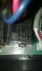
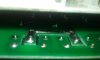
Just flip that PCB over and take a pic of where the relays are, and circle the one that's for "cool", that's the one we're interested in. The ac power traces will be wide, and the control signal traces will be thinner.
I'll edit the pic and circle where to test.
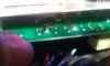
Yeah his looks like a nickel brass RTD, not good for immersion in nutrient solutions.OH it's been examined already. looked just fine. if you create an account with that website, Jolly Rancher includes a pic of his and it looks really rough. mine looks great.
Here's Jolly ranchers pic:View attachment 4039387
And here is mine:
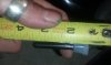
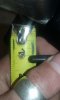
View attachment 4039379 View attachment 4039380 View attachment 4039381
Yours looks fine.
Airwalker16
Well-Known Member
Kind of a tight fit....Yeah, you just ones that have the same rating (voltage, amperage), the manufacturer doesn't really matter as long as they are of similar quality.
Just flip that PCB over and take a pic of where the relays are, and circle the one that's for "cool", that's the one we're interested in. The ac power traces will be wide, and the control signal traces will be thinner.
I'll edit the pic and circle where to test.
Yeah his looks like a nickel brass RTD, not good for immersion in nutrient solutions.
Yours looks fine.
Airwalker16
Well-Known Member
But if you look at my ratings, they sayYeah, you just ones that have the same rating (voltage, amperage), the manufacturer doesn't really matter as long as they are of similar quality.
10a-250v 10a-120v
50hz-COS.01 10a-24v
Everything else I’ve seen for sale or can even find a picture of, doesn’t have those same ratings. I have found only one source that sells the exact markings matching piece online. Do you have a link to one that would work that I could purchase if it’s bad?
Last edited: