Grow Project : Sun_burns Every Summer !

jubiare

Active Member
Did i miss something? put the pipe down guys :D
Yes that's right one has to put the pipe down for a vipassana course. They are tought around the world they feed you give shelter and teach you the technique.. For free.
Sorry for the boring topic but it does help to live better and gets the ego to rest a bit. It's free why not eheh.
Right I'll stop now, get the pipes back hihi
 

stardustsailor

Well-Known Member
aka " I should 've made a stencil ,from the start / beginning ...
Stupid me ...
Always in a hurry ...
...

Made a stencil ,out of thin ( ~100 microns / um ) copper sheet /foil ....
Same like making pcbs .... ( used packing tape for masking 'back' and 'sides'... )
P3106289.JPG
...

Applied solder paste ...Really nice ....
P3116293.JPGP3116294.JPG
...

Placed leds ,carefully ...
And on to hot plating at kitchen's stove ...
P3116295.JPG

Way better soldering than #1 panel's pcbs ....
P3116296.JPG..

.....
P3116299.JPGP3116300.JPG....

Pcb tested ( twice ) from 140 mA up to 700mA ..
No leds flickering or any other problems,what so ever ....
And they run really cool,also ....
Perfect ...


Also ,protective lacquer is going to be changed ..
I'm going to use that orange-red one ,used in coils / transformers ..
Better heat conductivity ,better insulation ,better abrassion / IPA resistant ..
( The T7 is not resistant to IPA* ,which is used used for cleaning / rinsing almost all the electronic parts ...)

* IsoPropyl Alcohol
 

stardustsailor

Well-Known Member
pardon stardustsailor... your leds test at what temperatures?... you use the kitchen al low temp to simulate the worst temp of led work on leds tests?

and... inexpert question...do you use the same quantity of soldier past using lead than free lead?...

...sorry my bad english...

Animo team SDS-GUOD... the best team i see... great work...
...Check Osram's suggested soldering profile for Oslon SSL ==> ssl profile ..JPG .....


I use kitchen to solder the leds ...
For nothing else .
(Ok...Not true ....And for heating copper etching solution.... )

....Never used Tin/lead/silver solder paste ...
Dunno really ,if there's a difference in "shrinkage " with the Tin/silver/copper one ...

But with the Sn96.5Ag3Cu0.5 and the use of stencil ,soldering with kitchen hot plate is just awesome !!! ....
 

stardustsailor

Well-Known Member
Since there's no growing yet ..(except my ego !! .....)
Let's see some more of " fail " ....
...As it evolves to something else ....
;-]
P3116303.JPG......
More evolving fail .......
P3116306.JPG

Oh ,here's the absolute fail ....
P3116307.JPG....

CRAPPPPP!!!!!!!
Total crap ,huh ?
Don't you agree ,some of you ?
P3116302.JPG...
 

stardustsailor

Well-Known Member
Now ....
Notice the difference in excess solder without (riveted/installed ) and with stencil used ...
Huge ..
P3116308.JPG.....


Pcbs work perfect and smooth from ~138,5 mA ...Up to 700 mA ..
(Only tested for few secs .. )

P3116309.JPG.......


I got the spare leds to fix the #1 box ...
Where's the spare time to do it ?
Have to find some ,I guess....
P3116310.JPG...
Fail is great ...
It leads to success ...

Which success then becomes a solid proof ...
....
(...About how stupid one can be ,amongst others .....)

To be continued ...
...
For sure ...
It is not over yet ...

...
My EGO has got really nasty ...
:fire:..
 

PSUAGRO.

Well-Known Member
Really pro shit SDS........keep it up friend, great contribution to this community IMO........who the Fuck would belittle this project??
 

Chronikool

Well-Known Member
Dont worry about the haters Stardust.....they are obviously jealous (or sexually frustrated). I dont see any fails or egos here. :)
 

jubiare

Active Member
Hey he mentioned ego, he said he reacts to things the same bad way.. He seemed unhappy and frustrated and suggested vipassana, which is my meditation technique, it is no jokes it's prob the best advice I had at the time when I went first time

Regarding ego it's direct to all of us coz despite the ego there's the "us", which SDS mentioned anyway in one of his posts. Ego can get over us but the technique helps.

Than if you wanna live like"me me me and only me" go on than.

Sorry for the vipassana thing I shouldn't have mentioned it on a ganja forum perhaps, I didn't mean to belittle the thread or hate the project at all
 

stardustsailor

Well-Known Member
Now...
Taking a brake for a spliff and some coffee (00:45 ..night is gonna be long ... )

Here's where we stand ...
Seeds have sprouted ...
Light should be ready yesterday ...

Up till now ...


mcpcbs placed on heatsink ...
(Have to be quick in hands ,with rivet tool ...Arctic Silver epoxy dries almost instantly .....
Really thin film achieved with using an old credit card ...)
Protective cups added also ...
(Central "purplish" pcb is going to be connected with the "master " buck ... )
P3116315.JPG......
Bucks soldered on fr4 driver pcb ...
pcb afterwards sprayed (copperside only ) with protective / insulating Teslanol T7...
Copperside (with thermal pours to aid cooling the bucks ...)
=>.....P3116316.JPG
Topside with connectors for power_fans_amperometer_dimming pot & leds output ....
=>P3116317.JPG...

pcb placed in position ,connected & ready to work ....
Couple of Ferrites added also to dumpen RFI/EMI from working fans coil/magnets.....
Everything is sprayed with protective / insulating lacquer to resist water vapours / salt / humidity / corrosion/ short circuits ....
P3116321.JPG...


From Outside looks like that ....
=> P3116319.JPG......
 

stardustsailor

Well-Known Member
I so much enjoy this ...
As it gets more and more complicated and intriguing ...

My heart was pounding like crazy ...
(My God....!!! Am I in love with that thing ? )

Box #2 was standing ready ...Just in front of me ..........
...P3126332.JPG


Pluged to the main PSU ,but not on power yet ....
Oh shit ....Just power the damn thing ,i thought ....

And so I did .........
P3126331.JPG

Pot at position ' 0 ' ,meaning fully turned anti-clockwise .....
~ 120 mA ........

Started turning slowly the $15 precision pot ,clockwise ....
10 full turns of fully analog dimming ....
From ~120 mA up to 700 mA ....
P3126330.JPG
Really precise dimming of leds ...
( And main PSU's pot dims the fans ...3/4 of a turn )
......

Warm Whites emit mostly at reds .....and some of FR/
NIR ...More than the other whites ....So ...they are not " bright " to human eye ....( lumens / candelas /etc )
For plants ,things are different ..(Watts / umol/sec ) .....

Reds 660 nm ,aren't either bright to human vision ....
Overall light seems ..."Easygoing " ..(unless you stare at leds ...You're f@ck3D .... )

Another fail ......
P3126325.JPG

One pcb is not lit ....
WTF ? ....

Searched .....
Tested ...
Measured ....

...Drivers ok!
....Solder/cable/pin connections ok !
...
It can't be the leds ...No ....
No ...No ....

I've tested 5 or six times that one particularly .....
I've had it for about 20" at 700mA without a heatsink ,placed on top of psu .....
It was that one .....
It was fuckin' working as smoothas it can be....
WTF happened ?


That's what happened ....

Reds are still mad at me ....
......P3126327.JPG.........


Why this red went off ?

Two main possible scenarios_at least ,of what I can think of right now ...:

#1 : During riveting on to heatsink ,rivets apply enough mechanical force to pcb ....
Possibly a weak or cold solder ,broke ,and closed circuit said "bye-bye " ......
Solution : Resolder the led properly .
-How ?


This is how :

(Have already done it couple of times ... )

-Take out rivets
-Unwire pcb ...
-Take out pcb (by force .....usually...)
-Clean heatsink from epoxy & rivet left overs/parts ...
-unsolder leds from ( possibly enough destructed )pcb...
-Make new pcb ..
-apply solder paste & solder the leds to new pcb
-place new pcb onto heatsink ..(glue & rivets ) .....
-Wire it ....
..
OH SHIT ,in short ....
.....
........
#2 ..: While testing leds,temps reached over ~217° C at pads .....
(-If so ,cooling the leds is the MAJOR issue for leds...Not an "an " ...." THE " .... )

Solder reflowed and possibly in an already weak joint (small amount of paste this time ) ,
solder moved from pad to another pad ...
/i.e to middle thermal pad ...
Lifting the led from previous contact ,when solidifying
....Too late ....Circuit is broken ...

Solution : As before ....
The ' Oh shit " thing ......


Or .......New ideas ,to be put in test ....

I need to warm up slowly and with a great control of temp ratio of increase/decrease if possible .....
The whole heatsink .......
Hmmmmmm......

With the the pcbs on ....
I have to go to the market ....
I'm out of butane ......
BoX #1 awaits to be fixed ....
I everything is going to be ok .....
Box #2 will follow .....

For sure building a light ,like that ,is for either the brave ones ,
or the total failures of life ...
No matter what/how/who/when/etc ... ....

I like it a lot ....

And giving up ,ain't an option for ME ...
('Cause of my huge ego ,you see .... )
P3126333.JPG

Aluminium is thermally conductive ,huh ?


But that means it , goes 'both ways '.....
Outgoing ......Heatsink ...
But ingoing ,also ....

Conductance & thermal contactivity ....
Right ?
 

jubiare

Active Member
Thats a brilliant looking Toy but I can see the difficulties with such a design..
Hang in there..
Patience is your virtue this Time
Good luck
 

stardustsailor

Well-Known Member
Thats a brilliant looking Toy but I can see the difficulties with such a design..
Hang in there..
Patience is your virtue this Time
Good luck

I prefer to think that everything's possible ....

I.e --...
One can learn to design 3D models ,using (*& learn how to use )assorted software ......
One can learn to design printed circuit boards ,using again the right software ..
One can learn to etch /make his/her own ordinary FR4 pcbs ...
One can learn to make his/her own Custom mertal core pcbs ...
One can learn to reflow at kitchen oven plate ...

(And forget about normal soldering,for good ...
I personally solder/ unsolder almost everything ,with reflowing in kitchen's plate ,by now ...
Pcbs,wires,resistors ,etc...Almost everything -Practising ,all the time ,to get some 'decent ' skills .
My hot air gun and my trusty Weller solder iron ,look really from " stoneage "times .....) ....

Why not being able to learn how to reflow /rework the mcpcbs when already installed on heatsink ?

Nothin' is impossible ...

There is not such a thing ,like "in yours dreams ,only " ....
In fact there's the place,where everything actually begins .....
In our dreams ..
Only ...


As for the difficulties ...
The other options are limited ...

-Have ordered / ready made the mc -pcbs with leds presoldered ( for ~ $300 each .... _3x mcpcbs =$900 ..Just for the mcpcbs !!!)

-Purchase mainstream market available mcpcb with led selection ..
Like : http://www.led-tech.de/en/High-Power-LEDs-Osram/Osram-Modules-c_206_209.html
Good and _relatively_ cheap choice ....
But not the kind of mcpcb design ,I " fancy " ....Although of high quality ...
And not mixed leds ...Kinda tricky to utilise ....
(Although I keep that option as an Ace on my sleeve .... ~30€ for 12 Oslons SSLs presoldered on a mcpcb is a great bargain .... )


-Stay on star mcpcbs forever ....,(Bliahhh....)
......

From the other hand ,I would not had wanted it to be easy for me ....
It would 've been a way boring thing ,to do.....
 

stardustsailor

Well-Known Member
Stoner way of thinking / solving stuff ....:

" ........

A metal core pcb consists of :

-a thin aluminium "substrate" / " core " ....
~ 1 mm thickness most common ....

-A thin dielectric layer of ~ 100 microns usually .
Most cases is epoxy resin doped with thermal conductive ceramic micro-particles .
(Alumina,beryllia,boron nitride ,etc )

-A copper "signal trace circuit " or " non signal thermal pour " layer .
Most commonly ~70-100 microns ....

Add before core layer another layer of epoxy ,doped with silver particles and 10 mm thickness aluminium ...
That's the heatsink and thermal glue .....


Reflow this sandwich ....
Which has fins at bottom ......30mm tall ....

...

a) Hot kitchen plate is out of question .......
Heatsink does not come in touch with stove and will take ages to reach reflow temps ..
No-no ....


b) Inside pre-heated oven ....
While good for preheating ,kinda awkward to rework the leds , being half inside the oven ,at ~ 230-240 °C ...
...Tricky .....


c ) hot oil bath ....level of oil just covering fins ...
Dangerous (self -combustion can occur .... ) and oil will hold high temps for more time than desired ....


d ) butane gas camping stove ....Fins act as heat conductors ,towards gas flame ....
Heat which is conducted towards heatsink base ...
Gas heater knob setting ,will adjust the rest ....

It seemed almost an "alien " practice to do same at kitchen stove plate ...
It proved way easy and really convenient ....

Might a humble camping gas stove ,be the ultimate "mcpcb on heatsink " rework tool ?

Never say never ....
 

stardustsailor

Well-Known Member
... I believe that not undesrtood well my previous post...

... my idea was test the leds with the warm pcb let's say 50º C looking for mistakes in weldings before giving them to the heat-sink...

a hot tests (say 50° C) by stretching the pcb
some tests on cold (say 10° C) by the contraction of the pcb

to test welds ... ¿are crazy ideas?

... are they my post what they bother you? ... my intention is to help if I bother you ...i not post more...

... I communicate badly since I do not dominate English ... Sorry...
No for God's shake,no ..
Your posts are not the least bothering ...

Now ,about testing in the stove ....
What's the point to "heat stress " the leds up to 50 °C ?
Not for testing the solder quality ,no ....
Phase change ( solid=> liquid ) occurs at 217°C for lead-free solder ...

Far from the 50°C range ...

Still I wonder ..
Is it possible for the Oslons ,soldered on a small pcb ,to reach in ~20 sec ,more than 217 C ,if no heatsink is attached at pcb ?
What exactly happened with that "solo " red led ?
It was working perfectly ,just before pcb was placed on the heatsink ...
Weird ....
 

stardustsailor

Well-Known Member
....
Box #1 :

Used camping gas stove ......And also a powerful fan (for cooling the heatsink ,after reflowing ) ...
Solder reflowed .....A tad trickier than kitchen stove ,but does the job just fine ........
Box#2 to follow ,to check what's wrong with it's red led,that doesn't lit ...

Box #1 ,needs wiring and it is ready !
P3136338.JPGP3136339.JPG.......

Box #2 :
Reworked the drivers pcb ..
Changed pcb ,for a ..better one ....
P3136343.JPGP3136348.JPG......

Soon ....
 

stardustsailor

Well-Known Member
Somebody fixed his toy ....

...Box #2 wired....And red led replaced ( it was fried ! ) .......

Box #1 can wait for later ....Just a bit ...


At ~ 140mA ....No leds flickering or else .....
It is easy to see which red led was replaced ,by the area (lacquer missing ) around it ...
P3136353.JPG......

Still at ~140mA ......
P3136351.JPGP3136354.JPG.....

Going at 350 mA ....
P3136355.JPG......

And at max of 700mA .....
P3136356.JPGP3146360.JPG........


Soon ,box #1 will be joining it's ....light .....
P3146362.JPG....


Phewwww ....
Finally made it ....
I wanna see some green growin' , now ....
Under my little led twin suns ....
 

SnotBoogie

Well-Known Member
Hurray SDS!!

Was that red bust in the same way as the one that fried before? with the burn on the lens?

Also, i only just noticed how much i like your color mixing....really nice placement.

Well done! Grow log time!
 

stardustsailor

Well-Known Member
Ain't doable with solder iron ,hot air gun ,reflow oven ,etc ....

Well ,Stardusty find out a really easy way to do it ...
...


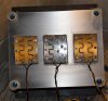
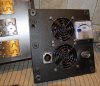
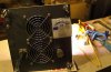
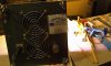
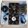
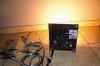
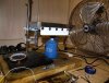
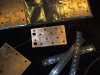
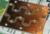
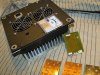
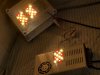
This is the reworking station :
P3146363.JPG.....

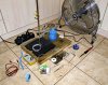
In order to rework mcpcbs placed on heatsink ,you need :

- A Small camping gas stove .Or how it is called ,anyway ....
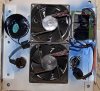
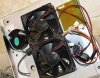
- A Powerful fan .
-Something to keep steady the heatsink ...I.e . a vice ...(I do not have one,right now !!!! ..)
- A solder iron .Or hot air gun ....
- Tweezers .
- High Temp.Thermocouple .Here used polymeter's type K thermocouple .Or IR/laser thermometer ,will do fine ...
- High temp tape .
-Anti-static bracelet (weared on other hand ,of the working hand ..Left at mi case ...)
- Solder paste ,flux paste & de-solder wick .
-Matches .
-Great caution ,not to cause yourshelf severe burns ...Or set your house on fire ....
Myshelf used to forge ,so I'm kinda used working with burning hot metal chunks ....


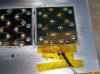
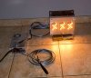
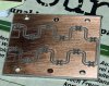
Now ....Place the gas stove under the area that needs reworking .....
You are supossed to have already placed nearby this area the thermocouple sensor with heat-resistant tape (i.e. Kapton )
P3146365.JPG......

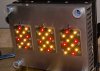
Fire the gas ,at max gas flow .......

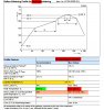
See how the temps rises slowly at the beginning ....

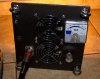
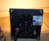
When temp have reached about 180°C ,get your stuff ready ....

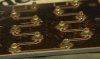
From here you can work the pcb with solder iron ...
You have to lower the gas flow .....
You have about ~ 40 sec time .
Then you'll have to switch off the gas ,turn on the fan and wait until it drops to 100°C .
to re-heat ,if there's more work to do .....
This is not for replacing leds ,but for removing excess solder ,soldering wires ,etc .....

For removing and replacing leds ,there are two ways ....
Depends on the situation which one to choose ...
Done both of them ...
Both work great ....

Way A " The Orthodox Way " ....

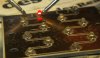
After temp has reached ~180°C ,let gas at max until ~ 240 °C .Then switch off .
You have ~ 20 sec to remove led and with a cotton battonette the excess solder from pad if any ...
When finish ,put your hand in front of pcbs and switch on the fan°C at max speed ...
You've to protect the leds from air ,because air stream might move them from position ...
Keep your hand there until temp drops at ~ 180....

Cool down heatsink to ambient ....

Place solder paste with stencil...
Place new led into position .....

Repeat the whole procedure ,until reflowing ....


Way B " I'm kinda stoned & bored " way ....

After temp has reached ~225°C ,lower gas a bit down ....
It will slowly rise up to ~240 ° .Idealy in ~ 20 secs ...
Remove led fast ...
Do not wipe off excess solder ...
Take new led with tweezers ....
Check polarity ...
Gently touch led bottom into solder flux .just a tiny touch....
Place quickly led in position ( pad ) ...
Adjust / trim into position fast ,if needed ...
Switch off gas...
Wait for 5-8 sec ...
Turn on fan at max ...With your hand protecting the pcbs ..Not just the replaced led...
Finished ...


Not very difficult ...
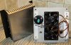
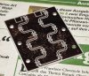
Well...Did it once on an empty heatsink :
-to check temp rise and drop rates ....
-Gas stove abilities in increasing temps for that exact heatsink ...
-Take a general idea ....

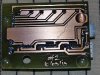
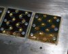
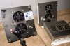
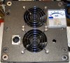
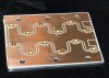
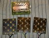
Second time did it on box#1 .....
Success ....

Third time did it on box#2 ...
Success ....

Great method ...

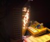
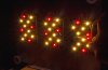
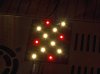
Working with leds ....
Never expected to set them on fire .....
Life's full of suprises ....


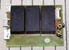
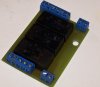
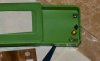
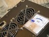
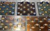
After the " surgery " ....
The removed "organs " ....
Kept for "autopsy" & "anatomy lessons "...
-Note : Althought they seem "burned" they're not ...
That carbon /brown burned color is because of solder flux of paste .
Once cleaned with IPA ,leds shine like new underneath this residue ..
In fact ..those ceramic type of leds ....They can tolerate enough "abuse " ...
They are made exactly for that ....
P3146364.JPG
 
Top