DiY LEDs - How to Power Them

GFS_Nic

Well-Known Member
Hi UKpeanuts,

Thanks you for taking the time to help me man.

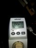
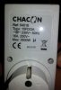
So, i tested each driver separatly, each one take more or less 102 - 105W when they're plugged on the new electrical strip. When it works normally they take more or less 150W each.
The new socket is in the same room that the previous one, so i assume they are on the same circuit but i can't be positif on that. I will deploy an extention from the previous socket and check it tonight.

a) Both drivers give me the same result when they're plugged individually (+-102W)
b) Sorry bro, even with the help from Google translate, i don't fully understand the question. I assume you are saying that it might be a problem from my house electrical circuit?

c) I will run all the tests that you suggest tonight. I will keep you inform of the evolution of the situation.

Thanks again for your help.

*: i forget to say that is quite hot in my grow room for the moment, we suffer a heat wave here. It's about 30°c and the weather guy announce a good 41°c for saturday, i think it's gonna make me melt...
 
Last edited:

UKpeanuts

Well-Known Member
Ha, well dude. Top marks for English, I assumed by your typing skills you were british or yankee!
anyway. .. (sorry about my poor english)

a) if both drivers are faulting in the same way / style it suggests the problem is upstream.
b) have you got 220V at your plug socket?
c) if you have 220V @ the socket, check you have 220V supplying the driver.
d) triple check your DC side.
e) totally disconnect your dimming pot. It might have failed.
 

GFS_Nic

Well-Known Member
Well, i didn't even think to plug the killawatt on the wall socket... Please forgive my stupidity, it should have been my first step obviously. Thanks for pointing that out. :)

I will keep you inform after my batch of test, it might help someone else too.
 

HydroDC

Well-Known Member
...for my pov ...off course the psu for fan needs an independent switch... but its only my opinion...
I think this is easiest and maybe best way as well.

robincnn, your bringing up failure points makes sense. If you have 1st switch for the fans' 12V power supply also provide power to the 2nd and 3rd switches for the 2 COBs, you can easily introduce one or two protections against failure points. Have the power to the 2nd and 3rd switches go through a relay activated by the PSU. If the PSU fails, then you'll also cut the power to the COBs. You can also wire in a pair of thermal switches attached to the CPU heatsinks that would kill the power to the COBs should the one of the fans fails.

I started a thread about this a while ago and got several excellent suggestions from the posts therein. (LINK)
 

GFS_Nic

Well-Known Member
@UKpeanuts

I found the guilty device in my setup, it was my f*cking timer! It's a Chacon (ref: 54000) mechanical timer:
20150629_211108.jpg
I had some doubt about it so i've tried another one, just to be sure, off course it was the same timer (same brand same series) so the reading was equivalent. After realizing that maybe it was not the best idea to run a test with the exact same model, i've finally tried again with another model of timer (same brand but different series, Chacon ref: 54016) and it's working really well right now:
Watt.jpg
The functional timer:
20150629_211209.jpg
The old one was a 9FD/3A type and the new on is a 15FD/3A type. I don't know what it mean and google doesn't want to help me to understand it.
Anyway, thanks again for your help.

Peace.
 

bmdiyh

Well-Known Member
What driver would I use to run 3 CXB3590 CD @ 1.4A. I am aiming for around 50% efficiency. If I have to I'll run them separately, but It would be good if I can run them all together with on driver with high efficiency.
 

GFS_Nic

Well-Known Member
@UKpeanuts

I did not open it yet, i need to find a "star" screw driver to open it, or a hammer, not sure about that. :)

I most definitly need a contactor, i just burned another timer, same problem similar symptoms. Now i need to understand what is a contactor how does it work and how can i install it properly and then get one and a new timer.
I try to figure out how to open this junk and i post a picture, but it doesn't smell like if something has burnt, i doubt that i will see something special.

Thank you for your concern.
 

UKpeanuts

Well-Known Member
so you take the switched L & N from your timer output and connect that to terminals A1 and A2 in the picture above.
Between A1 and A2 is a coil of wire wrapped around an armature, when energized its magnetic field pulls in a set of contacts. which are labelled as L1, L2, L3 in the picture.
I think the contactor above is ~ £15 and rated for 6A inductive. I would suggest Schneider/Telemeq or Siemens
 
Last edited:

GFS_Nic

Well-Known Member
You rock bro, i will get one tomorrow, hope to find a good one. You really are a helpful guy!
About the timer, here are the pictures:
20150630_205953.jpg20150630_210004.jpg 20150630_210013.jpg
I don't see anything special.
 

robincnn

Well-Known Member
If you have 1st switch for the fans' 12V power supply also provide power to the 2nd and 3rd switches for the 2 COBs
I do not want to turn power to COB and forget to turn on fan switch:o
I agree. Switch 1 for 12v fan should provide power to switch 2 and 3.
Also thermal switch sounds good. If thermal switch reduces power then thermal switch cools below cutoff temperature, again full power COB until it reaches its cutoff temperature point again.
 

tightpockt

Well-Known Member
Hello
Even me, has a noob, knew that you need a hlg-185-1400 for 4x3590 everyone speak about it everywhere on this thread. Just read a few post.
Almost everybody know it...
But to answer me about Vero10 there's no one's know!?!
May i run vero10 in parallel and anyone know a driver (not less than 90% efficient) for 8, 10 or 12 Vero10 and one for 1 Vero10 to get the vf of each cob if i have to pair them.
Thanks
Here's what you want for the Vero 10's https://www.fasttech.com/p/1714900
 

realm13th

Active Member
Does anyone else worry that some questions about doing a DIY build suggest a need for a better basic understanding of electrical principals and wiring practices than that which can be achieved by answering this or that discreet question? Do you worry that well-intentioned but ill-informed posters may get a few issues figured out with help from those more experienced yet still lack enough knowledge to safely and effectively do a build? Of course making an LED lamp isn't nuclear physics, but it isn't making brownies either.

I hope I offend no one.
I thought this was a thread for beginners. I've been browsing this site for some time before I made any configurations. Granted I am still new to diy led, but it is just a hobby. I have 3 builds using artic alpine 11's and the hlg 185's, using vero 29's that work well for me. I'm not trying to make the most efficient and game changing equipment out there. I like that this site is usually helpful and welcoming to people in all stages of understanding. I went ahead and built another light with the 320w inventronic driver and it works fine for my needs. There's no better way to turn people away from learning than with pretentious comments that don't add value. Thanks anyways.
 

UKpeanuts

Well-Known Member
You rock bro, i will get one tomorrow, hope to find a good one. You really are a helpful guy!
About the timer, here are the pictures:
View attachment 3451298View attachment 3451299 View attachment 3451300
I don't see anything special.
thanks for taking the time to take her apart, I know what moulded case equipment is like..
the micro switch (green box on bottom left) is actually only rated for 16(2A) - 2A inductive. when you switch on a inverter (ac-dc transformer) it will look like a short circuit for a few micro seconds allowing high current (heat) to melt the weak terminals in that switch.

I have been looking at the picture for a few minutes and can't really figure out how it mechanically switches, (although im no engineer!)
Are there any parts missing?

If you need any help setting up a timer contactor ask away, but if you have figured out this much I strongly suspect you will be fine :)
 

GFS_Nic

Well-Known Member
Hi UKpeanuts,

Yes indeed, some parts are missing, there's a little plastic crap that makes the link between the external and the internal switch. Finally i've chosen to buy an all in one device, a relay box switch (Davin DV14), it is made to handle up to 6* 600W or 5* 400W and up to 16amp. I think that It's basically a pre-wired contactor.
I wait a few days to see if it fails or not.

Thanks again for your precious advise. :)
 
Top