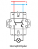
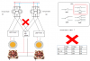
...im talking using bipolar switch to cut both wires (L) and (N) wires ... on this pic you can substitute the lamp with the driver for a lamp... or with the driver or psu for a fan... or both (connected in paralel conection)...
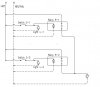
...there are models with double outputs connectors terminals ... one switch to control two devices at the same time,...
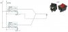
...you can use an bipolar switch with only one output combo (L and N terminals) and conect two devices (driver+cob and psu+fan) too... in paralel conection (Lcob with Lfan) (Ncob with Nfan) on respectives outputs (L or N switch terminals... (i prefer models with double outputs)...(independient terminal conector for independent wires...)
...i hope you catch better the idea...
...im too bad on paint ... sorry....
pd... im talking switches normally rated for 16 A on 220 v (AC) normally...
pd1...driver + cob + psu + fan ... its less the 16 A... ...Normally...
....normally i prefer check the consumes values for (drivers + cobs) and / or (psu + fan) too...
")
... but its only my opinion...
pd2....
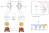
pay extreme attention when deal or work with live AC ...
...first a good auxiliar power box with a diferential switch (sorry i dont know her name on english) .... better search models with high sensivity...
10 mA...
...this is the
0,030 A version or model... im talking about the
0,010 A versions or models...The sensibility for the "diferential" on the principal box normally are
0, 300 A ... for these reason i prefer one more sensibility for our auxiliary power box...
...and for the magnetotermics... i prefer change the
C curves models by the
Z curves models... same reason ... more sensiblity than principal box models...
...this models are C curve version or models (
C16 and
C20
)... im talking about Z curve versions or models (
Z16 ...
Z20...etc)
...sorry i cant saw pics on google for better examples....
saludos


 ... back to the cavern...