Banana444
Well-Known Member
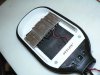
http://www.arcade-electronics.com/NTE-74-6SG3A-B-p/nte-74-6sg3a-b.htm
Im glad our dumb questions amuse you") This fuse is what I want then?
This fuse is what I want then?
Im glad our dumb questions amuse you
It means that when a single LPC-60-1400 driver switches 'ON' for a moment ,a 29 A (at 115 VAC ) inrush current "spike" will be drawn ,towards the driver ..Any one know what that means. LOL
For 115 VAC ( like U.S.A ) ,yes .http://www.arcade-electronics.com/NTE-74-6SG3A-B-p/nte-74-6sg3a-b.htm
Im glad our dumb questions amuse you

Awesome, thank youIt means that when a single LPC-60-1400 driver switches 'ON' for a moment ,a 29 A (at 115 VAC ) inrush current "spike" will be drawn ,towards the driver ..
The driver itself is well protected from that inrush current .(With the use of a Negative coeff Thermistor ,usually ..) .
If you will put a fuse that trips fast ( marked with F in glass fuses ,D or K on circuit breakers ) at 3 A ,the fuse will trip ,as the inrush current is ~x10 times (29 A ) the rated current of fuse ....
It will take a slow tripping fuse (marked T in glass fuses or B/C on circuit breakers ) that it will allow a short inrush
current current of x10 times the fuse's rated current (3 A ) to be drawn for a dt of a sec ,without the fuse to trip/burn ..
...
Ya, I like to see the smoke escape from a $40.00 cob too!So there's no point in putting a fuse on the DC side?
Sent from my SAMSUNG-SM-G900A using Rollitup mobile app

..Except maybe ,from another diode used as 'fuse ' ,ain't that right ?btw. no fuse is fast enough to protect a LED against over current.

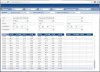
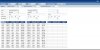
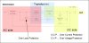
I am referring to the cxa3070 since it's spec sheet has min flux at both 85C and 25C under the bin group. It's the min flux@85*C in the bins that doesn't match up with what is calculated based on thermal droop chart from 25C, which is what I figured the tool was using...I took a look at the Cree tool and found pretty good agreement between the tool and datasheet.
First I took the 25C / 350mA test flux from a white bin N4 LED from the XP-E datasheet and got 62 lumens.
Next, look at the 'relative luminous flux vs forward current' chart for white on page 10 of the datasheet. I chose a drive current of 700mA, and found a 175% increase in flux from the test current flux. Calculated to 700mA, I now get 62 * 1.75 = 108.5.
I now need to derate this number for the junction temperature derating curve, which is found at at the bottom of page 8. This chart shows that I will get only 85% of the 25C output of this LED at 85C. I then calculate the final flux (0.85 * 108.5) = 92.2.
Both of these numbers agree well with what I calculated with the tool (see image):View attachment 3274760