DIY LED arrays to replace CFL's

methias

Well-Known Member
Well kids it's been a long time since I've been here (2010) but life happens you know.
First things first. Wow has this site changed. Cleaner, easier to navigate and search. I like it. Well done Rollitup.

Catching up;
My bonsai mom, while semi successful, bit the dust, but she lives on as a clone of her original plant still thrives. Ok lives.

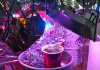
I have been a CFL mini cabinet guy from the time I was kicked out of our spare bathroom by my lady. In all fairness it is nice having the extra shower / tub for human use. I have fought with excess heat and the expense of replacing the CFL's as they become dimmer or die. After checking out many LED blogs and tech data sheets, along with grow light spectrum studies I decided to go for it and make some LED panels and give that a go.

From the start I realized that my limited knowledge in electronics :dunce: was nothing a bit of study couldn't fix.
I found a forum at http://www.electro-tech-online.com that helped me over some of the rough patches and so I have ordered parts and started on it.

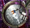
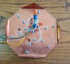
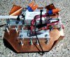
An aluminum U channel (from Lowes) that I am cutting into 12" lengths (it's 1" wide and about 3/4" tall) and bolting together (with spacers for airflow) for a heat sink.
A Meanwell APC 12-350 driver to power it.
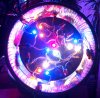
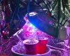
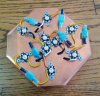
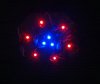
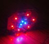
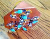
12 1W LED's (6 per side) red (625mm) and blue (465mm) for the first one. and 12 plastic reflectors (to narrow the beams from 140 degrees to about 25 degrees).

A bit of wire, solder, flux, screws, heat paste, and time bringing the total for the first one to about $30.00 .

Thats about the cost of big CFL at Home Depot with less heat and more specific light wavelengths (by a factor of way) as well as an expected longer lifespan:clap:.

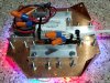
It's gonna be a bit ghetto but I have high :bigjoint: hopes.
My lady told me "Aww Bullwinkle, That trick never works." So I am hoping to prove her wrong.:leaf:

Parts are showing up daily and it's time to start. I will try to tear away long enough to get some pics as I go so you can see how it goes.

Stay tuned,
Same bat channel,
Same bat time...
 

mauricem00

Well-Known Member
seems a little light on power. most people are using a mix of warm white and cool white leds with good success. I have just started my first led grow using 3 cool white and 4 warm white 10 watt COBs. on a single plant. you could also use warm white and cool white bulbs.I use T5HO in my grow closet and set this up in the corner of another closet for a comparison grow.I am using cheap chinese diodes from ebay for the test and if it works than I will buy good diodes. you can grow with 1 watt red and blue diodes but you probably will not be happy with the results. you need the fuller spectrum provided by white leds and high power leds will give you better penetration.have you read the DIY led forum. many experienced growers and a lot of good information.
 

methias

Well-Known Member
I intend to make 4 arrays. Since my last post I have completely rethought my design and I have some white 35K & 55K LED's and yellow (590nm) on the way. I am playing around with 1 watt LED's as I have a pair of very small cabinets (one veg & one flower) and I can get loads more light with less heat (by a factor of way) to deal with.
Yes I too am using cheap ebay LEDs but you gotta start with what you can afford and move up as you can.
I decided that I wanted the ability to swap out LED's easily so I am using molex connectors between each LED. That allows me to change out colors (or burn outs) as I get them. Still waiting for my 10W 12V 900mA driver so I assembled what I have and wired on a 9V battery to test it out. This one has 1 blue and 2 reds in each of the 3 parallel strings.
IMG_20140417_152018.JPGIMG_20140417_152107.JPG IMG_20140417_152304.JPG IMG_20140417_152339.JPG IMG_20140417_152454.JPG
It may not look like much in the pic but it is very bright.
As I said when the white arrive it's a simple task to swap individual LEDs out to give me 3w, 3b, 3r. on this one.
It's a start.
 

methias

Well-Known Member
Shit...
I have two in the flower room one 3 weeks in and the other less than 1.5 weeks from done and the young one is popping balls. had to harvest the old one early. I scoured the herm and cut off all the balls I can find but two of them were open so this one will have seeds. On the plus side I hear that herm seeds are nearly all female so I guess I'm gonna have some seedlings next year.
 

Positivity

Well-Known Member
I'm no expert either. Did notice some things though. Why the screw barely grasping the star? Might be better to just use some thermal adhesive pads on them stars if the holes are too far apart.
One other thing is the connectors are dangerously close to the lens of the led..could end up frying some wires or burning off the plastic insulation. I'd just solder them together...it only takes a few seconds to undo a solder...takes longer to make a good plug by far. Would really clean up that led area and make it safer. I'd even electric tape those wire nuts just because

Good start..fun hobby..just gotta be as safe as possible too
 
Last edited:

SupraSPL

Well-Known Member
Hey Methias good on you for trying DiY. I know you did not ask for constructive criticism but in hopes of giving you shortcuts to success here is what I can advise. Although copper is great at spreading heat fast, even with just a few watts there is not enough surface area in the design to maintain a low Tj (junction temperature inside LED). Since those LEDs are relatively low efficiency to begin with their efficiency really gets punished by a high Tj. Also their lumen depreciation will accelerate and they might actually burn out. For comparison the heatsink surface should be around 30C. CPU heatsink/fan combos are a cheap way to go and can even work with passive cooling to some extent. Cheap on eBay or brand new on Amazon for $9-$12.

The next low hanging fruit is the interface between the LEDs and the heatsink, it is important to attend to. The LEDs stars are not flat and neither are heatsink surfaces, so if there is no thermal compound the heat cannot escape the LED junction. The heatsink temp would appear low but that is only because it is all concentrated in the emitter. Cree recommends flattening the LED star and the heatsink surface to 1000grit for a good thermal transfer and I recommend a thermal paste like Prolimatech PK3.

In your first post you mentioned a 350mA driver and in your second a 900mA driver. Without an aggressive heat management change, I suspect they would burn out if run at 900mA. Good luck and please keep us updated on your experiments and results!
 

methias

Well-Known Member
I'm no expert either. Did notice some things though. Why the screw barely grasping the star? Might be better to just use some thermal adhesive pads on them stars if the holes are too far apart.
One other thing is the connectors are dangerously close to the lens of the led..could end up frying some wires or burning off the plastic insulation. I'd just solder them together...it only takes a few seconds to undo a solder...takes longer to make a good plug by far. Would really clean up that led area and make it safer. I'd even electric tape those wire nuts just because

Good start..fun hobby..just gotta be as safe as possible too
The screws have (home made) silicone washers to prevent shorts, The wire is rated at 300 degrees and so I am not worried about them near the heat of the LEDs. Before wiring I always solder the stripped ends. I have been using these wire nuts for over 10 years and never had one back off. Since I have already prepped all my LEDs with the molex connectors (male = + / female = - ) and tested all my solder connections for any shorts I can reconfigure, replace (bad LEDs) or reassemble at will as inspiration hits me.
Thanks for the input as safety is much required when playing with electricity.

Hey Methias good on you for trying DiY. I know you did not ask for constructive criticism but in hopes of giving you shortcuts to success here is what I can advise. Although copper is great at spreading heat fast, even with just a few watts there is not enough surface area in the design to maintain a low Tj (junction temperature inside LED). Since those LEDs are relatively low efficiency to begin with their efficiency really gets punished by a high Tj. Also their lumen depreciation will accelerate and they might actually burn out. For comparison the heatsink surface should be around 30C. CPU heatsink/fan combos are a cheap way to go and can even work with passive cooling to some extent. Cheap on eBay or brand new on Amazon for $9-$12.

The next low hanging fruit is the interface between the LEDs and the heatsink, it is important to attend to. The LEDs stars are not flat and neither are heatsink surfaces, so if there is no thermal compound the heat cannot escape the LED junction. The heatsink temp would appear low but that is only because it is all concentrated in the emitter. Cree recommends flattening the LED star and the heatsink surface to 1000grit for a good thermal transfer and I recommend a thermal paste like Prolimatech PK3.

In your first post you mentioned a 350mA driver and in your second a 900mA driver. Without an aggressive heat management change, I suspect they would burn out if run at 900mA. Good luck and please keep us updated on your experiments and results!
Constructive criticism is always appreciated.
Yes I thought of this.
I am using aluminum C channel on the back (attached after the pics) and thermal compound between the LEDs and copper as well as the C channel and copper on the back. The temp (after 6 hours running) is only 114 F so I think it's OK.

I made an error when buying parts. I got a 350mA driver and 300mA leds. Had to add a parallel resister (2W 570ohm) to bleed off the extra 50mA or my leds would most certainly fry. I got the 900mA driver and did 3 duplicate parallel strings so each string now draws 300mA and a 400mA fuse in each string so if one LED dies the fuses will save the other LEDs from the upped current.

I saw on other sites about the less than flat bases. I did some sanding and used thermal compound.

This prototype (and two other 10 watt arrays) got me ready for the next step. I am making a 36 Watt array that is going to be 6" x 18" with between 30 and 33 LEDs. I have started and I will be posting pics of my progress in a few days...

Now I gotta go search and neuter my hermaphrodite. Again and again and again....:wall:
 

SupraSPL

Well-Known Member
Gotcha, sounds like you are well on your way. I got a bunch of herms in my new test batch so I am doing the same thing, plucking balls all day lol.
 

methias

Well-Known Member
Hello again all,
I finally got two of the 300mA drivers that took the slow boat from China (literally I think) to here. I pulled the 350mA driver (which is slated for the 36 watt array) and installed a 300mA driver. The array got brighter! I must have done a slight overkill on the bleed resisters but better safe than....
Here is what this array looks like with the U channel heat sinks attached. BTW I remeasured the array temp after 12 hours running (just prior to shutoff) and the highest temp reading I got was 104 F.:bigjoint:
IMG_20140427_081000.JPG IMG_20140427_081047.JPG

The cost for this 10W array;
Driver $2.04
U channel from Home Depot $10.00
10 x 1W LEDs < $4.50
The copper plates were just hanging around in my garage (from an old business) as were a crap load of screws, nuts & molex connectors < $10.00 (wholesale)
Plus misc pieces not listed above brings this array total to about $30.00 :mrgreen:

As I said before, it's a bit ghetto but it works.
And to mauricem00, I am still waiting for the 300mA 3000-3300K and 5500-6000K LEDs to arrive. Apparently the last slow boat passed the one with the white LEDs on the way here. Once here I will swap out 4 LEDs on this panel with 2 of each of those. I do like the idea of full spectrum for my girls (and herm).

Till next time;
Vape on dudes and dudettes :peace:.
 

methias

Well-Known Member
Gotcha, sounds like you are well on your way. I got a bunch of herms in my new test batch so I am doing the same thing, plucking balls all day lol.
Good luck with that. Diligence is the word of the day.

Well the damage is done.
The herm seeded itself here & there but my diligence has kept any other balls from opening. As stated before I hear herm seeds are nearly all female so I will have some good seeds to work with. Thats good because my cloning abilities are less than stellar.

May all your seedlings be ladies..:weed:
 

SupraSPL

Well-Known Member
Glad you got your parts together. Do you happen to have links to those drivers? I got one like that from Fasttech but they sold out.
 

SupraSPL

Well-Known Member
Thanks! This is the one I got from Fasttech that turned out yo be 88% efficient and capable of up to 52vF. Very cool for those running strings very soft. The page says 650mA but it is a typo, it puts out about 310mA.

The Ebay seller you linked has one just like it
 
Last edited:

mauricem00

Well-Known Member
some of those chinese companies can be a little slow.on the other hand I received an order from led-queen in just 5 days ( chinese supplier ebay) I just received a 5 meter 5630 strip light ($12 from ebay free shipping) I cut it into 2 foot strips, attached it to a thin aluminum plate and wired the strips in parallel.the panel drew 2.4 amps at 12 volts and if the philips data sheet is correct I am getting 3000 lumens (104 lumens per watt)which is not bad efficiency. when the carrier pigeon finishes his break and gets here from china with my second strip I will be making a second panel and using the two for side lighting. but with a mix of CW and WW strips this might make a good top light for a small grow cabinet. very evenly distributed lighting so no shadows on leaves beneath the canopy and very low heat so can be kept close to the tops. just an ideal for your consideration.we are all just experimenting and hopefully having fun as we learn in this rapidly evolving field.
 

mauricem00

Well-Known Member
Thanks! This is the one I got from Fasttech that turned out yo be 88% efficient and capable of up to 52vF. Very cool for those running strings very soft. The page says 650mA but it is a typo, it puts out about 310mA.

The Ebay seller you linked has one just like it
great driver I have been looking for something like that the resistors in these strip burn up 25% of the power. if I felt ambitious I could shunt the 100 resistors on these strips and run 7 2ft strips in series on one of these drivers. this would bring the efficiency up to 134 lumens per watt. and reduce heat by 1/3 not bad for a 3000 lumens $12 dollar light and a lot of tedious soldering ( low budget but lots of time "sweat equity")
 

methias

Well-Known Member
Quick question;
Where does it say that the lights must be above the plants?
why not surround them from all sides, front back left right?
My cabinet is very short and the girls stretched more than expected. If I side light I add 4-5 inches grow height.
Any opinions on that?
 

SupraSPL

Well-Known Member
I tried vert growing with bare 600 HPS bulbs and although it increases efficiency by removing reflector losses, the plants tipped toward the light so it had the same effect as overhead lighting.

So now when a plant gets too tall I bend it sideways and tie it down. The leaves reconfigure to face the light and you get a better yield. So if you add side lighting it might not look to good at first but the plant will adjust for it.
 

mauricem00

Well-Known Member
have you considered placing mylar on the ceiling and adjusting your lights so that a portion reflects off the ceiling and on to the top of the plants? my lights are above my plants but I find that the lower leaves grow toward the wall until they get past the canopy and turn up toward the main light,I have also been playing with strip lights. some micro growers use these and they could be attached directly to the ceiling and take up less than 1/4 inch. a little more blue light could help reduce stretching as well
 

methias

Well-Known Member
Ok,
I'm back again. Iv'e been putting together a couple arrays and this one says ghetto all over it.
But guess what... It turns out to be the coolest (lower temp) of them so far.:fire:
Simplicity and low cost.
Parts;
1 8" aluminum disposable pie pan.
12 1W LEDs ,,,4 blue, 1 red, 3 yellow, 3 warm white, and 1 bright white
1 300mA 14W driver
scrap pieces of U channel that I had not thrown away yet.
Screws, wire, thermal paste, and pipe cleaners.

I laid it out, drilled the holes, attached the U channel to the back (to make it more rigid and dissipate more heat), attached the LEDs and presto. This is what I got..
The back
IMG_20140504_154147.jpg
The business end
IMG_20140504_154008.jpg
And along with two of the copper back boys.
IMG_20140504_154256.jpg IMG_20140504_154320.jpg
The girls are reacting well to this.
Yes , Ghetto. I know. but it works and the fan for the ladies keeps all the LEDs nice and cool.:peace:
 
Top