DIY E-Nail

biscuithead

New Member
Thanks man I know I have it all wired right but maybe pictures will make me realize something I may have messed up. The wire going thru the ssr isn't really one wire it's just showing the power right and it's two wires haha because that's the only wiring I have different
 

budbro18

Well-Known Member
haha sorry guys i was kinda showing the flow of electricity. You just wire a wire in through the 2 spot on the ssr and out the one spot with a separate wire. No connection

Also, the ground goes into the screw hole for mounting the SSR. im pretty sure it doesnt matter which side you do it on. Pictures in a few! I hope it helps. I didnt use any different colored wires but it should be easy enough to see.
 

budbro18

Well-Known Member
Hopefully these help but honestly i dont think they will. Shits so crammed in there i cant even tell what goes where at this point.

Ill be makin a blown out one with no box that just shows where all the connections go. Might even grab some white and red wire to go with my black wire. Or i might just cover all the wires in shrink wrap thats different colors haha.


budbro18

Well-Known Member
Unfortunately all the U connectors i used for the SSR and shit have red covers built in so try to go by the shrink wrap you see thats white or red to tell you the charge haha. The wires for the SSR are both white so dont get those confused with negatives.
 

biscuithead

New Member
Ok I thought I had it all set up right but I only used two wire screws one split into two on positive and 4 wires combined off n brass to pid and ssr maybe you could help me clarify but I think the switch connections are the only thing throwing me off what did you connect the other nut screws to
 

budbro18

Well-Known Member
Can you post some pictures so i can see?? Its really hard to think about it but you onlly need 2 wires coming off the switch one for the coil and one for the PID.

Make sure your SSR positive and negative are both hooked up to the right connectors.
 

biscuithead

New Member
Sorry I can't seem to add pictures right now but what are the other wire nuts connected to because I have two and you have like 4 and that's our only difference from what I can see sry pics won't load
 

budbro18

Well-Known Member
Theres 5 but only 3 are used as splits the other 2 are used to connect wires from the coil to the internals

1 is for the ground split (power inlet), 1 is for the negative split (power inlet/switch), one is for the positive split (switch output), 1 is for connecting the ground to the ground of the coil, 1 is for connecting the negative to the negative on the coil.

The hot of the coil has a connector on it wired straight to the output of the SSR.

I could have probably cut 2 or 3 of them out if i wanted but i didnt know how many wires they could safely hold so i tried to limit the hot to only a few per nut and tried to use as few as possible because i wanted all those connections to be secure.
 

biscuithead

New Member
hey i have it set up like you but i dont have a pos going to the coil only two neg should i switch to having output + go to coil instead of two neg i cant imagine its getn powered by two negatives right
 

tharealmclovin

Well-Known Member
WHat did you use to make the connection of the coil to your box? I see you hardwired it, like I did. What is that piece called...it looks nice.
 

budbro18

Well-Known Member
Yeah 2 negatives will not work well. hahahaha

The coil positive and negative for power are interchangeable so dont be afraid to wire it up!

And im not sure what theyre called mclovin but its an electrical connection clamp type thing ive seen them on a bunch of things to keep wires still so they dont get yanked out.

ill try to look them up.
 

LiquidJunglist

Well-Known Member
Heres my wiring diagram. Theres less wires because the power inlet/switch are all in one so i just had the lines in the picture coming straight off the switch.

Reds are hot, blues neutral/negative, green are ground, orange are SSR, purple are TC


Heres the power inlet/switch wiring, already posted but i like having em in the same spot.
Reds hot, white negative/neutral, white with black line is ground (far right wire)


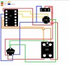
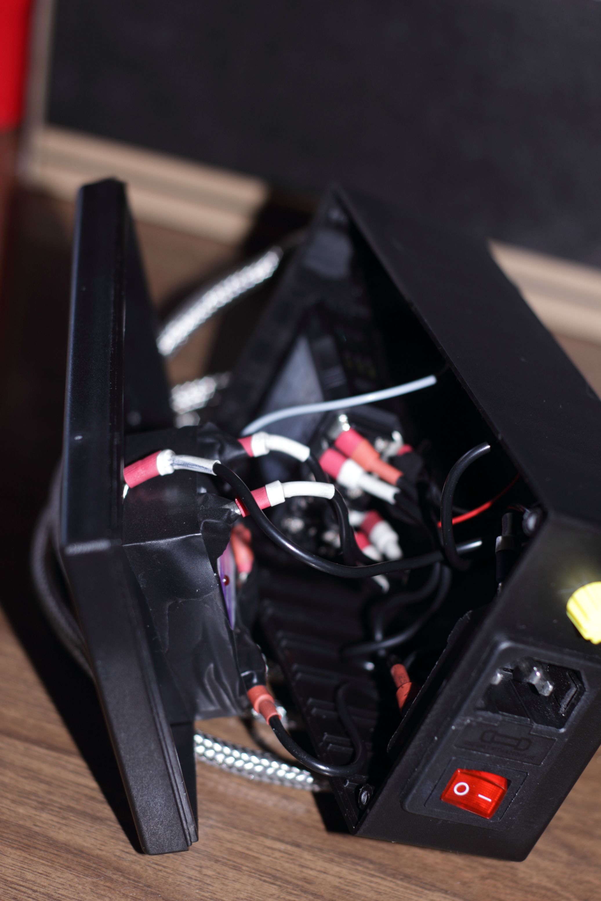
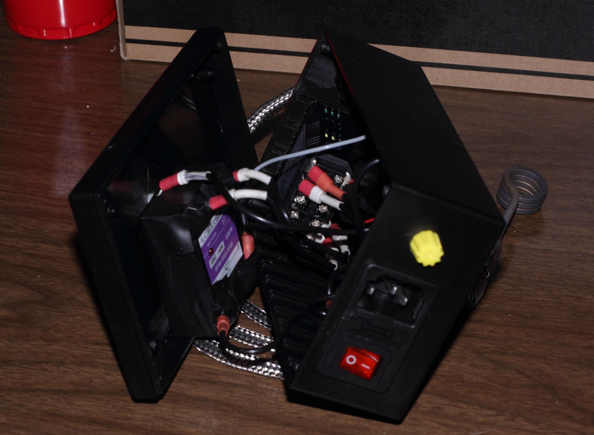
Ill probably be tearin open the box today and takin some pictures. Looks like a rats nest but should help a little more.

And to anyone who hasnt bought their project box get one about an inch longer than the one i listed. It all fits... but barely.
Ok another question ok exactly where are each of these wires leading to from the inlet/switch wiring.. I know the PID and the Coil both need positive and negative power so are you splitting the wires from the inlet/switch wiring too go to each or is there 2 wires coming off the +, - and the Ground.. Hope I make since.

When I look at the diagram I see the 2 P, 2 N and the 2 G coming off the inlet/switch. Sorry if I'm asking a question that might have already been asked but I had to ask.
 

biscuithead

New Member
Is there any way to check my ssr since I've had it the light only flipped on once for a split second when I wired it as soon as it came in the mail is it supposed to have the light on when working maybe I need a new one
 

budbro18

Well-Known Member
Sorry the wiring diagram kinda skips the power switch thing. I made it like that because not everyone is going to use the power switch/fuse/inlet combo that i use.

Basically i use 1 connector and 1 wire coming off of the hot then connect that to the switch and have the single wire output of the switch connect to 2 wires with a wire nut. 1 goes to the PID for power, 1 goes to the SSR input and comes out to go to the coil.

For the negative, i use 2 connectors and 2 wires since i have to bridge from the negative input to the switch which has no negative output. so the 2 white wires you see (not the far right one with the line on it thats ground) are actually wire nutted together with 2 other wires. One goes to the PID negative, the other goes to the coil negative. I was comfortable with this because its not the hot even though if it came loose and touched the hot id be in trouble but theyre some tight wire nuts so i should be good.


For the ground i just use 1 connector and only connected 2 wires to it. 1 for the coil ground which used another wire nut, and one for the SSR ground.

I found this easier because i could have single short wires coming off the switch and then just attach any length of wire running off those into the rest of the body.


Im not sure what you can do to check your SSR. Maybe try hooking it up without the hot coming out to your coil. Thats what i did to test my pid worked fine and to set the temp so when i first plugged it in it wouldnt blast to a high temp and fuck my coil.

Did you get it from auber?? If so you either still have the connections wrong or you might have burnt it out somehow. Connecting the 2 negatives shouldnt have done anything bad so double check your SSR to PID connections and make sure theyre the same.
 

budbro18

Well-Known Member
Yeah it blinks. whenever its on its letting power through. The PID algorithm looks like a sound wave so and the top of the crest it turns off and the bottom it turns on. Probably before the bottom but either way the light should be flashing.

Hope everything works out! You probably had it right the first time and your SSR was just bad. Or maybe hooked it up wrong once then right but it was already fried.
 

budbro18

Well-Known Member
Im hopin to soon! Puttin in orders for a 5pk of coils and the supplies for 5 of them! I want to do some pre order shit because my money is so tight between making vac chambers and runnin a bunch of tane the past few weeks. Glad this shits finally back!!

Did you just one one box or multiple?? I have my first one built and have had a few offers for it but its not so pretty lookin so i might not be able to let it go haha.


Either way within 2-3 weeks i should have the first set of 5 built.
 

LiquidJunglist

Well-Known Member
I'm also glad the site is back up. Seems smooth on my iPad.

I should be getting all my parts ordered this week I hope, I'm in the same boat brother money is TIGHT.

I've been looking at the new pre wired coils from our buddies in China. But I'm kinda eh about there XLR I would much rather use a Neutrik XLR because I know there the bomb because I'm a Audio Engineer and the BEST XLRs are from them. There a mega solid when you click them into each other.

So I'm getting a case that is a bit bigger from Hammond so I'm likely going to have enough room to wire everything. I can't wait to get it!!! Later I might design a case in a 3D program and have it made on Ponoko there very cool.
 
Top