200 X Cree XP-G3 on one board

Guys,

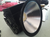
I'm looking for some help to source and select some better power connectors. As you can see from the image I mounted them to close to the entry hole and the cables look under undue stress, moving them further away from the entrance would help but there must be some better or best way of getting this right.

I also dont like the blue and brown colored cable should I use some black or white heat shrink?

Thanks in advance
Willpcb-xp-g3.png
 
Last edited:
ok but you gotta tell us about that monster light first!
This was the first test board of 200 Cree XP-G3's I've been waiting to get my hands on a roll for a few months, they finally got delivered last week I was able to lay them down quickly, linked them up to some Mean Well Drivers and and a PC cooler heat sink.

No reds added on this run but there will be on the next board. I also want to move to a copper board and sort out the power connectors, the optics I want to find something with a much lower profile, and change the heat sink to something custom and better looking.

I also need to understand the 2 screwdriver dials on the drivers as I have no idea what they do, or how to set them, I'll take some photo's and some readings on this tomorrow.

I also have access to an integrated sphere so more more readings from that to come too.

Some quick and basic PAR readings

2ft = 2000 umol
3ft = 1267 umol
4ft = 885 umol
5ft = 64 umol <=== Huge drop!
6ft = 47 umol
7ft = 36 umol
8ft = 27 umol
No power (ambient light only) = 8 umol
Power at the wall = 500w

Outdoor natural sun light 11:45am Blue Sky, blazing hot day in the middle of summer = 1700umol

All readings taken with a Sun System PAR Meter
Distance measurements were taken from the chip not the edge of the reflector.


Some quick temps.

Ambient room temp of 33 (it was a hot day)
The drivers measure max of 53 (without being connected to the heat sink)
2ft away from the lamp a piece of card measured 40
main heat sink backing plate is measuring 48-50
board center max is 81.7 with the glass covering

All readings are in Celsius and taken with a laser pointer


pc-cooler.png
 
Last edited:

CobKits

Well-Known Member
damn, you hand-soldered that? impressive!
I also need to understand the 2 screwdriver dials on the drivers as I have no idea what they do, or how to set them, I'll take some photo's and some readings on this tomorrow.
usually one is voltage and one is current
 

CobKits

Well-Known Member
nothing wrong with those terminals, theyre just in a bad spot. rotate them 90 deg and they would work great
 
damn, you hand-soldered that? impressive!

usually one is voltage and one is current
It would indeed haven been super impressive if I had hand soldered them by hand! I admit I had a friends robot do the work for me, kinda cheating I know.

So turn the Voltage down till the light goes out then then tweak it up a little? and leave the current on its max setting? Any advice on how to set these would be great.
 
Last edited:
nothing wrong with those terminals, theyre just in a bad spot. rotate them 90 deg and they would work great
I really want something that at-least looks more pro and something less fiddly for my fat fingers to connect would be nice.

What do you think of these http://global.wago.com/en/products/product-catalog/pcb-terminal-blocks-connectors/pcb-terminal-blocks/smd/index.jsp and the brochure is here http://www.wago.com/infomaterial/pdf/60291132.pdf?_ga=1.19518780.529913019.1472376203
 
Last edited:
A spectrum king knock offf
Thats a bit harsh buddy, the same heatsink was used as my starting point because they are easily available at the local market. I literally walk out of my door and there is a market with over 100 little shops and every single one of them stocks the same range for this model. Just search google images for "500w PC Cooler LED High Bay"

The PC Cooler housing is the worlds most popular heatsink for high bays by far, the designer who holds the design right to it made millions from the design, due to the sheer volume they shift, and the crazy price they charge for it, it's so popular they now license the design to other factories to keep up with the demand.

Spectrum King, myself and countless others have learnt allot from pulling apart and studying these amazing heatsink. If you ever get the chance get one, run it, test it, pull it apart, consider how it was manufactured and in what order it was assembled, the material and finishing selections, its so fucking mind boggling how good it is.

And then we move on, we design and manufacture something thats specific to our needs as apposed to lighting the outside of buildings and football stadiums.

What else is the same?
 
Last edited:

CobKits

Well-Known Member
It would indeed haven been super impressive if I had hand soldered them by hand! I admit I had a friends robot do the work for me, kinda cheating I know.

So turn the Voltage down till the light goes out then then tweak it up a little? and leave the current on its max setting? Any advice on how to set these would be great.
turn the voltage all the way up (it will only take what it needs) and use the current to dim.assuming your design is good and your chips are seeing too high of a current youre good. extra voltage wont hurt them
 
turn the voltage all the way up (it will only take what it needs) and use the current to dim.assuming your design is good and your chips are seeing too high of a current youre good. extra voltage wont hurt them
Thank you @KobKits!
I do struggle to understand why Mean Well even put on a voltage dial if its best cranked to full, assuming thats what it is for sure. The current I can understand is useful, I wonder what the adjustable range is, I'll get the multi meter on it in the morning and make sure I'm not pushing them to hard.
 
I have 4 spectrum kings
Well then you know how good the heatsink is and I'm sure you will have thought to yourself while staring at it, how did they get the copper heat pipes into the fins, how were they attached, what was painted in what order, how did they get the copper flat in the block. How do all the little bent parts fit into each other so perfectly. How does the power cable get to the board and maintain a waterproof rating? As I said before the PC Cooler heatsink is amazing.

I dont know what LED's you have in your Spectrum King or which size of the heatsink you have?? I'm confident its not the XPG3's as I've been on a waiting list and the most I could get was 1000pcs last week, you may have the 500W PC cooler but maybe the 400w version.
 
Last edited:

CobKits

Well-Known Member
Thank you @KobKits!
I do struggle to understand why Mean Well even put on a voltage dial if its best cranked to full, assuming thats what it is for sure. The current I can understand is useful, I wonder what the adjustable range is, I'll get the multi meter on it in the morning and make sure I'm not pushing them to hard.
well for example if you wanted to limit current you could dial voltage down so it cant rise over a certain point if that makes sense. most drivers are combination constant current/constant voltage depending on how you operate them
 
well for example if you wanted to limit current you could dial voltage down so it cant rise over a certain point if that makes sense. most drivers are combination constant current/constant voltage depending on how you operate them
I'm with you, I'm going to go back to my workings to get them both dialed in just right.

thank you again @KobKits
 

Uberknot

Well-Known Member
Serious heat there. heat sink looks like some of the old sever passive heatsinks modified.

It will be interesting to see how they pull the heat out of the area's.

I'd like to mount em on my car for people that dont turn their brights down ;)
 
Top