DIY E-Nail

fatalflowers

Active Member
Yup thats what the PID stands for Proportional, Integral, Derivative

From my understanding its like a wave on an oscilloscope. You want it to be nice and even after the start up point. The X amount of power put in every X amount of time should directly line up with the rate at which the heating element cools/heats. Too strong and the coil will overshoot its designated temp and prematurely ware itself out, too low and the coil will drop temps really easily and struggle staying at the temps you want.

Ive watched a few videos explaining it on youtube but my math is horrible so i got lost once they showed an equation that was 90% letters. hahaha

According to shipping everything should be here by saturday unless it gets slowed down and since most of it is USPS thats highly likely. But monday at the latest for all parts including the stuff from auber.
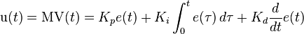
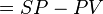
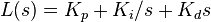
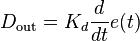
Don't suppose you could post the equation and the numbers you need to plug into the equation. I'll have a go at the maths for you.
 

budbro18

Well-Known Member
PID controller theory[edit]
This section describes the parallel or non-interacting form of the PID controller. For other forms please see the section Alternative nomenclature and PID forms.
The PID control scheme is named after its three correcting terms, whose sum constitutes the manipulated variable (MV). The proportional, integral, and derivative terms are summed to calculate the output of the PID controller. Defining
as the controller output, the final form of the PID algorithm is:


where

: Proportional gain, a tuning parameter
: Integral gain, a tuning parameter
: Derivative gain, a tuning parameter
: Error

: Time or instantaneous time (the present)
: Variable of integration; takes on values from time 0 to the present
.
Equivalently, the transfer function in the Laplace Domain of the PID controller is


where

: complex number frequency
Proportional term[edit]

Plot of PV vs time, for three values of Kp(Ki and Kd held constant)
The proportional term produces an output value that is proportional to the current error value. The proportional response can be adjusted by multiplying the error by a constant Kp, called the proportional gain constant.

The proportional term is given by:


A high proportional gain results in a large change in the output for a given change in the error. If the proportional gain is too high, the system can become unstable (see the section on loop tuning). In contrast, a small gain results in a small output response to a large input error, and a less responsive or less sensitive controller. If the proportional gain is too low, the control action may be too small when responding to system disturbances. Tuning theory and industrial practice indicate that the proportional term should contribute the bulk of the output change.[citation needed]

Integral term[edit]

Plot of PV vs time, for three values of Ki(Kp and Kd held constant)
The contribution from the integral term is proportional to both the magnitude of the error and the duration of the error. The integral in a PID controller is the sum of the instantaneous error over time and gives the accumulated offset that should have been corrected previously. The accumulated error is then multiplied by the integral gain (
) and added to the controller output.

The integral term is given by:


The integral term accelerates the movement of the process towards setpoint and eliminates the residual steady-state error that occurs with a pure proportional controller. However, since the integral term responds to accumulated errors from the past, it can cause the present value to overshoot the setpoint value (see the section on loop tuning).

Derivative term[edit]

Plot of PV vs time, for three values of Kd(Kp and Ki held constant)
The derivative of the process error is calculated by determining the slope of the error over time and multiplying this rate of change by the derivative gain Kd. The magnitude of the contribution of the derivative term to the overall control action is termed the derivative gain, Kd.

The derivative term is given by:


Derivative action predicts system behavior and thus improves settling time and stability of the system.[10][11] An ideal derivative is not causal, so that implementations of PID controllers include an additional low pass filtering for the derivative term, to limit the high frequency gain and noise.[12] Derivative action is seldom used in practice though - by one estimate in only 20% of deployed controllers[12] - because of its variable impact on system stability in real-world applications.
 

fatalflowers

Active Member
Blimey going to have to brush up on the maths skills it's been a while. Cheers for posting this budbro. I'll post up the numbers as soon as I'm done. probably be a couple of days as definitely going to have to relearn some maths. It's been about 8 years since I did any maths like this. But I'll get there don't worry. be happy.
 
I ever talked to our PID controller man, he said that too, But too professional. Easily it has something to do with the date you set for P(Proportional Band) I( Integral timer) D( Derivative Time)
 

fatalflowers

Active Member
Hi Budbro do you have any values you'd like me to plug in to the equation? or are the ones on the graphs your values?
Can definitely see why you had problems working this out. I have, no I did have a good understanding of the calculus maths involved ie integration, differentiation but that equation is well mind boggling I will get there eventually. So what temperature is your ideal set temp? Any other numbers you could give me would be helpful too. Also just learnt there are 3 different types of pid algorithms used so also depends on the algorithm your controller uses. Do you know which one yours is. Should say in the manual.
There are 3 different types of PID algorithm

  1. Ideal (also called "ISA")
  2. Series (also called "series" or "interacting" or "analog" or "classical")
  3. Parallel (also called "non-interacting", "independent" and "gain independent)
 

fatalflowers

Active Member
Hi still relearning calculus. But could do with the preferred temperature you like it set to and if you've had it running how long it took to get there. (I think). But I will get there. Will post something soon as I've learnt everything needed and have the numbers.
 

fatalflowers

Active Member
Although it looks like budbros' auto method worked very well and I'm not sure how much better actually using the pid equation would be if any better at all.
 

Daniel710

Member
Need sone help I have power temperature but it stops at 89 and I tried to put it in auto tune to see if it would help but I let it go for about five hours and never stopped blinking so if any one has any suggestions that would be great?
 

MR Zulu

Well-Known Member
Need sone help I have power temperature but it stops at 89 and I tried to put it in auto tune to see if it would help but I let it go for about five hours and never stopped blinking so if any one has any suggestions that would be great?
what PID are you using? What's the Volt & Watt rating for your coil?
 

MR Zulu

Well-Known Member
Need sone help I have power temperature but it stops at 89 and I tried to put it in auto tune to see if it would help but I let it go for about five hours and never stopped blinking so if any one has any suggestions that would be great?
personally it sounds like you have your TC and power mixed up. "I have done that before and had the same exact outcome" ...... just a reminder though...... Auto tuning should NEVR take more than a few hours depending upon what you have plugged into your PID but we all are using relatively small coils and should only take a hour tops , also make sure no fans or central heating and cooling systems are on in the room you plan doing your auto tuning in, it can throw off the auto tunes algorithms and your life of your coil could potentially be shortened.
 
Last edited:

MR Zulu

Well-Known Member
yeah check your TC- and TC+ and that they aren't mixed up with your two power wires (note: You don't have to worry about - , + on your coil power to the coil itself. But make sure your TC- & TC+ don't get mixed up, won't get a proper temperature reading and will burn out coil.) it's what it sounds like, can you see a very dim lit light on ssr if you look closely, or in the dark? If so your just pumping 12v into it and that means you got a few wires mixed up. but I'm certain that you have done a redundancy test of all connections? I.e. No lose or crossed wires.
 

Daniel710

Member
I went over every thing and everything is correct besides no light on the ssr and this is a new ssr so could it just be the ssr?
 
Top