V series "Tetras"

stardustsailor

Well-Known Member
Let's hope that Guod will notice the initial post ...

Now...
Although,comparing to Guod,I'm a "novice" to electronics ...
I've thought about it a bit ...And manage to design some very "raw " circuits ...

Actually there are two -at least approaches - to the issue.

Approach #1 : AC side.
In this approach ,no actual dimming is done.
It leaves the dimming DC circuit as is.
But it has some limitations .
It takes as basis ,that each COB is driven by it's own CC driver.
Simply it switches the first COB ,when a timer IC switches on the LED light fixture .
After a certain-adjustable- time it switches the second ON the second COB ,
then after some time it switches the third and so on.
Up to 10 drivers/COBs can be handled withg this circuit.
(More than 10 can also be handled ,but it needs more parts.)

So ,actually no dimming is done .
The irradiance is gradually increased (in so many "steps",as the number of cobs /drivers.).
Quite "rough " approach ,but that was my first -quick- idea...

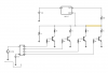
So here is the schematic :
ACside_option.JPG

Basic Parts :
4x mechanical or solid state relays.
4x NPN transistors ( BC547 or 2N3904 )
1x LM555 timer IC
1x HCF4017B Decade Counter
1x 10 MegaOhm potentiometer
1x 47 uF electrolytic Capacitor
1x 1MegaOhm resistor
1x 10K resistor
4x resistors (value still uncalculated ,but probably in the range to 1-10 K will be fine )
3x 10-100 nF capacitors (for bypassing noise )

I 'm not sure if everything is alright .Later I will note down some of my concerns.

How it works : When the timer switches on the LED grow light ,the Fan power supply switches ON also.
The LM 555 timer IC is then powered up,also.
As it is configured in ASTABLE operation ( http://www.555-timer-circuits.com/operating-modes.html ) ,
the timer will output a PWM signal of ~ 50% duty cycle ,from its OUTPUT pin (3) to the INPUT (CLK ,pin14) of the
HCF4017B Decade Counter.Every time a new "high" signal is reaching the CLK pin of the decade counter ,
it's output pins will be HIGH ,starting from OUT 0 (pin 3) towards OUT 9 (pin 11) .
As V series Tetras fixture ,features four drivers (and four COBs ) ,not all OUt pins are connected.
Only the Outputs 1 ,3,6 & 9 are used ( pins 3,7,5 & 11 respectively ).
Every output pin is connected to a NPN transistor ,which powers a relay .Each relay powers up a LED driver.
At the last relay (#4 ),before it's base resistor ( R4) ,a line lifts the CLOCK INHIBIT (pin 13)of the decade counter to HIGH.Thus the decade counter stops alternating it's outputs ,and the output 9 (pin 11) stays HIGH .
The circuit will reset itself ,when the LED grow light is switched OFF and back ON again (hopefully ).
The LM 555 timer's frequency is adjusted by the 10M pot , from ~ 1min up to ~10 minutes .
( http://www.ohmslawcalculator.com/555-astable-calculator )

So ,actually the minimum " rise time" is 9 minutes ( 1st driver ON ,after 3min the second,at 6min the third and after 9 min the fourth driver.).The maximum "rise time is ~90 min ( 1st driver ON ,2nd after 30 min ,3rd after 60 min ,4th after 90 min )

Concerns:
-The 555 timer will continue it's PWm astable operation.Will this affect the operation of the decade counter?
(As it's input (CLK,pin 14 ) will continue receiving signals from the timer)

-A fifth relay (or MOSFET/transistor) has to be used to stop the 555 timer ,instead of clock inhibiting the HCF4017B Decade Counter ?

- Will inrush current of the driver deteriorate the contacts of a mechanical relay (sparking ) ?

-The high threshold resistance (1M ) & pot (10M ) used for LM 555 timing allow only for low currents ,thus any induced noise can be an issue ?

.....
I just hope Guod,sees all that and comes with a far better solution,than this one ....

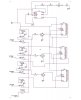
Next one, comes the -more complicated- Approach #2 : DC ( DIM ) side.

Cheers.
:peace:

Edit :
I've already spotted a mistake :the transistors will switch OFF ,every time the decade counter will proceed to the next output.Instead of transistors ,MOSFETs probably have to be used .So this schematic is wrong.(WAYYYYY Wrong !!!!)
:wall: :cuss: :dunce: :wall: :cuss: :dunce: >:( :wall: :dunce: :oops: >:( :wall: :evil: :dunce: :finger: :wall: :cuss::wall:
 

Attachments

Last edited:

stardustsailor

Well-Known Member
Not desirable? I see. You want an analog counter. Cascade reset counters that select from a resistor bank?

I see. Let me think about this.
Cascade reset counters that select from a resistor bank ?
:shock:....

It seems like a rather nice idea ...
Hm....

Let me think about it ..
Any proposed schematic or circuit ?
Every output that goes HIGH ,has to remain HIGH (LOCKED HIGH ) ...

And to be honest ,I do not trust much the idea of MOSFETs switching ON and "locking " at ON state the relays ,as the MOSFETs gate capacitance may discharge with time ,even if their gate is not brought to LOW.
 
Last edited:

stardustsailor

Well-Known Member
Right, the counters don't reset, before the entire system resets each day.

Of course, you can recount it the other way at the end of the day to back the light down and have a reset system.

I'm not particularly interested for the " end of the day gradually irradiance decreasing " part
On the contrary ....
....
If you study that pdf from NASA...

(Use wikipedia / google to understand the role of the enzymes and metabolites mentined -i.e. like RUBISCO- ,if your biology skills are not so good .It helps rather a lot )

You will understand some basic plant biology "things"....


If a rapid on-set of irradiance is the case "no starch is produced for several hours ",

Thus no sucrose also.....
plantsinaction.science.uq.edu.au.png

http://plantsinaction.science.uq.edu.au/edition1/?q=content/2-4-1-starch-and-sucrose-degradation

Starch
is mainly used during the "night" (lights OFF ),
to sustain the metabolic procedures of a plant,when is not
photosynthesizing and for healthy root growth.

http://en.wikipedia.org/wiki/Starch


Sucrose from the other hand is used ,when the plant is photosynthesizing
(For plant growth and ... for flowers / fruits )
http://en.wikipedia.org/wiki/Sucrose

From my point of view ,is somewhat better for starch to be produced early ,when " day" begins,to feed the roots and make "reserves " for the "night" following and the rest of the day ,the plant can produce sucrose for actual growth and massive flowering .

Now...During flowering especially :

"Similarly, if irradiance remains high at the end of the day starch
synthesis stops and sucrose synthesis and export nearly double".

The way I see it ....

A gradually on-set of irradiation will aid for starch production (healthy roots & night energy reserves) ,avoiding light & water stress ,while remaining a high irradiance at the end of the day ,as it doubles sucrose synthesis & export ,will aid for vigorous plant growth during vegetative stage ,while during reproductive state (flowering) it promotes (double production of sucrose,but no starch produced ) for massive flowering .

Still,that's a theory ....
What remains to be done is the actual testing ....

And as the NASA study ,states at pg. 31/412 :

(...) Effective lighting should produce plants that perform according to the goals of the project.
For example, for physiological studies the plants probably should exhibit morphology and
physiology similar to that found in field-grown plants.

For other projects the criteria will obviously will be set according to the reason for raising the plants .(...)


In our case :
Flower buds =>more flower buds =>most flower buds !
Trichomes=>more trichomes=>most trichomes !
Resin=>more resin =>most resin !


That's why i trust that a "soft on-set "of irradiance ,will compensate for the high irradiance at the end of the day.
Up till now having a rapid irradiance on-set plus a high irradiance at the end of the day ,
may have caused light & water stress ,induced early photoprotection and inhibited greatly the starch production...
Plant's do acclimate,of course ..
But ,I just want to see what happens if you give them a " gentle push" towards a certain "acclimation" ...
Towards a certain "behaviour" ,regarding Carbon allocation ...
I'm just being curious..
Maybe I'm wrong ...
But if i'm not ...He-he-he..:fire:...Mua-ha-ha-ha-ha ....:weed:

Ohh...I need this "soft-irradiance on-set " circuit board ASAP !

GUOD !!!!!!
O brother ,where art thou ?


Cheers.
:peace:
 
Last edited:

AquariusPanta

Well-Known Member
Starch is mainly used during the "night" (lights OFF ),
to sustain the metabolic procedures of a plant,when is not
photosynthesizing and for healthy root growth.

Aha! This would explain so much about the stringy abnormalities of my feet lately, as I've been waking up during the middle of the night and gorging myself with bags of potato chips while the lights are turned off.

I think I've finally evolved into my truest potential.... a plant!

I really have little to no idea on what it is you are trying to discover here, Sailor, which isn't anything new ;-), as you're always exploring uncharted territory with your cunning imagination, but I felt like stopping by to post a little creativity (and humor if you're merciful).

Also, I've noticed lately that you're posting longer and longer posts... leading me to ask you whether or not you intend to write a book one day, unless you have already done such a thing.

I personally believe that every soul should aim for writing no less than one book in their lifetime.

O and @Doer, I'm sipping on herbal tea (true blueberry).
 

Doer

Well-Known Member
Yeah. I can see that. Sucrose export bias. I missed the significance of that.

I am drinking Brita Filtered Water. :)
 

ReeferDance

Well-Known Member
Aha! This would explain so much about the stringy abnormalities of my feet lately, as I've been waking up during the middle of the night and gorging myself with bags of potato chips while the lights are turned off.

I think I've finally evolved into my truest potential.... a plant!

I really have little to no idea on what it is you are trying to discover here, Sailor, which isn't anything new ;-), as you're always exploring uncharted territory with your cunning imagination, but I felt like stopping by to post a little creativity (and humor if you're merciful).

Also, I've noticed lately that you're posting longer and longer posts... leading me to ask you whether or not you intend to write a book one day, unless you have already done such a thing.

I personally believe that every soul should aim for writing no less than one book in their lifetime.

O and @Doer, I'm sipping on herbal tea (true blueberry).

I really enjoy sitting on the sidelines as SDS hashes out his experiments. :grin:

Every time I enter this thread I know it will be saturated with information.

Awesome stuff to think about, I always wondered how the plants react to 100% ON/OFF, to a more sun-like rise/set.
 

churchhaze

Well-Known Member
The rate of starch production is correlated to the amount of sugars and fluxes being stored as well as the level of cellular Pi.

In the morning, the leaves have converted ~100% of the starch stored in the chloroplasts into sugars, and burned them. Starch iodine tests show this to be the case. This means that sugar levels are very low in the morning, and thus it makes sense that the rate of starch production would also be low until the plant could produce photosynthesis for long enough to get sugar levels up. The plant still burns glucose during the night that it gets from re-mobilizing the starch so it can be transported to energy sinks like buds and roots, and newly expanding leaves.

So how does the plant know how fast to convert starch into sugar? The plant actually uses the length of of the previous nights to know how fast to remobilize the starch. As long night lengths stay consistent, it doesn't matter how much starch the plant managed to accumulate during the day. it will burn all of it during the night. (obviously the more starch you can get in the leaves, the faster the rate of respiration will be at night)


churchhaze

Well-Known Member
This is really great stuff.

http://www.plantphysiol.org/content/155/4/1566.full

"Figure 1. Schematic representation of the pathway of starch biosynthesis, its subcellular compartmentation, and distribution of flux control in photosynthetic leaves (A) and heterotrophic tissues (B). The reactions of the pathway of starch biosynthesis are catalyzed by the following enzymes: 1, phosphoglucoisomerase; 2, PGM; 3, AGPase; 4, SS; 5, SBE; 6, starch-debranching enzyme; 7, inorganic pyrophosphatase; 8, Suc synthase; 9 UDP-Glc pyrophosphorylase; 10, fructokinase; 11, ATP/ADP translocator; 12, Glc-6-P/Pi translocator; 13, cytosolic AGPase; and 14, ADP-Glc/ADP translocator (steps 13 and 14 are highlighted to be specific for cereal endosperm)."


Fig 2. Regulation of plastidial AGPase by multiple mechanisms allows starch synthesis to respond across a range of time scales to a variety of physiological and environmental stimuli. Plastidial AGPase is a heterotetramer that contains two large (APL; 51 kD) and two slightly smaller (APS; 50 kD) subunits, which both have regulatory functions. Top, Allosteric regulation by 3PGA and Pi operates in a time frame of seconds to adjust the rate of starch synthesis to the balance between photosynthesis and Suc synthesis in leaves in the light and Suc breakdown and respiration in tubers. Left, Posttranslational redox modulation involves reversible disulfide bond formation between Cys-82 of the two small APS1 subunits, leading to changes in AGPase activity in response to light and sugar signals in a time frame of minutes to hours. The signaling components leading to redox modulation of AGPase involve Trx and NTRC, which are linked to photoreduced Fdx and interact with different sugar signals. Right, In Arabidopsis leaves, APS1 and APL1 have been identified as potential targets for reversible protein phosphorylation. More studies are needed to investigate the in vivo relevance of this mechanism and the underlying plastidial kinase network. Bottom, Transcriptional regulation in response to changes in carbon and nutrient supply allows more gradual changes in AGPase activity, which may require up to days to develop. Red font indicates inhibition, blue font indicates activation, and question marks indicate unknown (see main text for references)."


stardustsailor

Well-Known Member
Thank you ,brother Guod!
I wish it was a "Yotta-like" button ,specially made for ya !

So ,Staircase -Generator ...
But it needs some sort of MCU ...:-(
(Somewhere deep inside me ,I had a fear about that ....)

http://www.dbecker.de/sites/default/files/staircase.pdf

Another ,issue that came up ,is that ,if the circuit was to be done at the DC side of a driver ,
I do not want really ,to start dimming from 0% of load.
Meanwell suggests as minimum output the 10% of max Io (minimum= 10 K res for a single driver )

So ,i've to say that I'm more inclined to switching ON the LEDs/COBs one by one -in steps ,
instead of starting from really dimmed down LEDs/COBs increasing their output to preselected Io .

Thank you very much Guod.
You've presented a very good solution,indeed.
Still it needs some sort of MCU...
(Not that bad at all,but is something I want to avoid ,for quite a few of reasons .)

This is really great stuff.

http://www.plantphysiol.org/content/155/4/1566.full

"Figure 1. Schematic representation of the pathway of starch biosynthesis, its subcellular compartmentation, and distribution of flux control in photosynthetic leaves (A) and heterotrophic tissues (B). The reactions of the pathway of starch biosynthesis are catalyzed by the following enzymes: 1, phosphoglucoisomerase; 2, PGM; 3, AGPase; 4, SS; 5, SBE; 6, starch-debranching enzyme; 7, inorganic pyrophosphatase; 8, Suc synthase; 9 UDP-Glc pyrophosphorylase; 10, fructokinase; 11, ATP/ADP translocator; 12, Glc-6-P/Pi translocator; 13, cytosolic AGPase; and 14, ADP-Glc/ADP translocator (steps 13 and 14 are highlighted to be specific for cereal endosperm)."


Fig 2. Regulation of plastidial AGPase by multiple mechanisms allows starch synthesis to respond across a range of time scales to a variety of physiological and environmental stimuli. Plastidial AGPase is a heterotetramer that contains two large (APL; 51 kD) and two slightly smaller (APS; 50 kD) subunits, which both have regulatory functions. Top, Allosteric regulation by 3PGA and Pi operates in a time frame of seconds to adjust the rate of starch synthesis to the balance between photosynthesis and Suc synthesis in leaves in the light and Suc breakdown and respiration in tubers. Left, Posttranslational redox modulation involves reversible disulfide bond formation between Cys-82 of the two small APS1 subunits, leading to changes in AGPase activity in response to light and sugar signals in a time frame of minutes to hours. The signaling components leading to redox modulation of AGPase involve Trx and NTRC, which are linked to photoreduced Fdx and interact with different sugar signals. Right, In Arabidopsis leaves, APS1 and APL1 have been identified as potential targets for reversible protein phosphorylation. More studies are needed to investigate the in vivo relevance of this mechanism and the underlying plastidial kinase network. Bottom, Transcriptional regulation in response to changes in carbon and nutrient supply allows more gradual changes in AGPase activity, which may require up to days to develop. Red font indicates inhibition, blue font indicates activation, and question marks indicate unknown (see main text for references)."

(...)
CONCLUSION
There have been recent advances in our understanding of the regulation of starch synthesis in response to environmental and metabolic signals. However, our knowledge of the signal transduction cascades remains far from complete. Specifically, there is a lack of knowledge on the molecular identity of the sensors, the intracellular signaling pathways, and the integration between photosynthetic and metabolic signals. Work in the last years also extended our understanding of the role of posttranslational protein modifications and protein-protein interaction in the regulation of starch synthesis. Evidence is emerging that starch synthesis is regulated by reversible protein phosphorylation and protein complex formation. However, it remains unclear whether these mechanisms are significant in vivo and whether their roles can be generalized for different plant species. More work will be needed to achieve a better understanding of these important aspects of the regulation of starch synthesis and to apply this knowledge for crop improvement.
(...)

All i know that this is a new relatively unknown territory-especially for us LED growers ,
as our beloved solid state lighting offers countless possibilities and alternatives.
From the other hand " not knowing where you're going,you can't be lost " :P..
I just have a strange -nice- feeling ,that something good is awaiting there,
hidden under our nose ,almost in front of our eyes.
Of course I could be wrong about it ,big-time...

Still,regarding light,as the primary source of energy of our green ,silent friends ...
We've been concentrating mainly at two of it's aspects :Quantity ( irradiance) and quality (spectrum).
We have almost forgot about a Titan named "Saturn" ....:razz:
( Latin name of Cronos /Cronus/Kronos and yet, is the same as Chronos =Time )

NASA pdf pgs 19 & 20 / 412 :

Physiologically Imuortant Measures of Light

Photosynthetic photon flux or PPF
(ex. pmol ma2 s-I), a combination of irradiance and spectral
quality,
is a measure of the photosynthetically active photon irradiance (PAR or
photosynthetically active radiation defined as the irradiance between the wavelengths of 400 and
700 nm). PPF is the maximum energy available and only a small proportion of the photons
actually are used to assimilate carbon.


Time course of diurnal PPF and integrated diurnal irradiance, combinations of irradiance and
duration
, have important effects on photosynthetic carbon metabolism and its regulation. Of
particular importance is the rapidity with which the light begins.


Maximum irradiance level and the duration of high irradiance are important aspects of the time course
of diurnal PPF, potentially affecting the degree of photoinhibition or photoprotection, both of which can lower
the efficiency of light use for photosynthesis
. It is important that these aspects of irradiance
generally be similar to those under which the plant developed.


Daytime spectral quality and end of day spectral quality are a combination of quality and
timing.
Not only does light drive photosynthesis but irradiance that extends beyond the range of
400 to 700 nm affects plant morphology, physiology, leaf display and chloroplast orientation.
Properties of light that affect growth and morphology of the plant, in turn, can affect
photosynthesis.

Photosynthesis generates a positive feedback system in which photoassimilation
contribute to further growth and so on. The compound interest aspect of the production and
growth of leaves obviously is affected by plant properties such as leaf area and thickness, which
are regulated by light.


Photoperiod, the duration and timing of the irradiance, has marked effects on plant physiology
and morphology, including carbon allocation, root to shoot ratio and reproduction.
A
combination of duration and irradiance comprise the integrated diurnal light energy that
determines both the total daily assimilation of carbon but also affects morphology and
physiology of leaves.


The four properties of light, alone and in combination, are important to consider in the design
and evaluation of performance of plant lighting systems.
Responses to the various aspects of
light are conditioned by adaptation, the genetically determined range of possible responses.
For example, plants that are adapted to growing in the sun will have a certain maximum
photosynthetic capacity which will be considerably higher than that of a shade plant. On the
other hand, plants adapted to grow in shade will be able to survive at a lower photosynthesis rate.

Within the range of the adaptive possibilities, plants undergo acclimation to actual conditions.


Cheers.
:peace:
 

Doer

Well-Known Member
I was thinking more of timer delay switches. i know there is a limitation on counting time with a 555. They are only good for something under about 10 minutes.

This is a 300 second timer on Ebay for $8.00

NE555 Timer Delay Switch 1-300 second 5-12v DC input TIME OVER RESET

I don't remember the intervals you were thinking about, but since you don't want last light backed out, you can use these, one shot then reset, timer circuits in series. Tr1 begins as soon as L1 illumination, and starts to tick off the L2 wait duration. The logic is like this.

Main timer starts system and L1 fires up
L1 starts T1
(delay)

T1 starts L2
L2 starts T2
(delay)

T2 starts L3
L3 starts T3
(delay)

T3 starts L4

This is only 3 timers. They cascade. And if you need more time, use more timers.
 

Doer

Well-Known Member
@stardustsailor
I know you've already stated that you don't want to use a MCU. Is price the only reason? Or should we avoid using it in our designs?
Ehhhhh..... I can see now what he means. ATINY85 is very cool. All the ATMEL are trick processors. A little ole thing called RISC. Reduced instruction set. Very reliable.

There is only a few of these types, the most famous was SPARC from Sun Microsystems, (bought by Oracle) It is opposite of the idea of Intel Chips, CISC. Complex instruction set.

With RISC, most of the logic is hard coded in the chip. So, we don't need these complicated software instructions, to prep general purpose registers and set up the logic paths in the chip.

This is why there are only a handful of easily memorized commands for Arduino. It is based on ATMEL RISC processors.

BUT!!!!, programming these suckers is not easy, unless you have special equipment.
I have used the Arduino Open IDE, the Eclipse Plugin, and the ATMEL Studio IDE.

It is WINDOZ that fails. Specifically the USB protocols are crap. I'd have to re-boot the laptop each time. Boring.

So, I gave up on integrating ATINY85. The code is so easy, but the shake down of the hardware is not a job for a laptop.
 

stardustsailor

Well-Known Member
Well,I have came up with a new idea...
Hope it works ,though ..

(Guod,I know I'm being somewhat cumbersome-pressing ,but please if you find some time ,
please check the following schematic in case that something is really wrong ...Thank you ,in advance )

AC_SIDE_NEW.JPG


How it is supposed to work :
When the LED light is switched ON ,by the wall timer ,the +12 VDC source powers up :

1) One LM555 timer is switched ON at astable operation .This is the "clock" of the system .
It can be adjusted to it's frequency.It's output is commonly connected to the inputs of three decade 4017 counters. ( U2-U3-U4) .

2) The first relay ,which powers up the first driver ,thus the first COB lights up at it's pre-selected irradiance level.

Now...

The first relay is a Douple Pole -Single Throw.One pole swithes ON the 1st driver ,as mentioned before and the second pole ,through a base resistor (R3) switches on a NPN transistor (Q1) .
The latter powers up the first 4017 Decade counter (U2), which has only it's last output (pin 11) connected to the next relay .The 555 timer gives a clock PWM signal with it's adjusted frequency being multiplied by 10 ,from the decade counter(s).

When pin 11-of the first decade counter U2- goes HIGH two things will be happening (hopefully) :

1) The next relay in sequence(relay 2) switches ON .
2) The CLOCK INHIBIT input of the decade counter U2 ,goes HIGH,
thus the decade counter stops it's operation right at that point and it's last output (pin 11) remains locked at HIGH .

As the next relay (relay 2) is powered ON ,the next driver switches ON ,too.
As also ,via the transistor Q2 that switches ON , the whole procedure repeats its self with a new decade counter (U3), firing up the next relay (relay 3) and at the same time "locking" it's output to HIGH .

Same procedure with relay 3,transistor Q3 and the next decade counter (U4).

The last relay (relay 4 ) is a simple single pole /single throw ,as there's no more drivers to be powered up .
In case of more drivers to be switched on ,it had to be ,of course a Douple pole/single throw and more transistors (Q4,Q5,Q6 and so on ) as also more decade counters should be there also (U5 ,U6,U7 and so on ..)

I hope it works ...
( The ceramic noise bypass capacitors (10-100 nF) ,close to every VCC of each IC used ,
are not shown at the schematic .Also a 47uF electrolytic close to VCC of the LM555 is nice to be there. )

Cheers.
:peace:
 
Last edited:

Devildenis69

Well-Known Member
Lot's of great info here guys thx :mrgreen:
as I run differents wavelenghts on different timers, I'm very intersted in those things ...

I also believe in benefits of dimming, that's why I'd like to understand this point:
-The pre-selected irradiation level is achieved via resistors ,as you probably already know.
So PWM or Voltage dimming are not desirable..
I've read that pwm dimming produces kind of flickering, (visible on a video recording), but as this 3 in 1 dimming function is just an input command, I used to believe that the 3 types of command should produce the same result, am I wrong ?

or maybe your point was about the powering-on moment, as pwm is not something constant, depending on the driver technology, it could run at full power for the 1st milliseconds, but still voltage dimming shouldn't be concerned ...

There's obviously something that I'm missing ...
 
Top