pelzroo
Well-Known Member
Found this on the net after my third timer/powerstrip meltdown. I've made several already, they are easy to put together and work great.
How to Build a Four Light Grow Light Controller for Less Than $80
Anyone that has more than two 1000 watt lights in their home has probably run into the problem of how to supply power and turn them on and off. A standard 120 volt circuit in your home has a 15 amp rating, that means one light. Note: I will be using the term "120 volt" and "240 volt" to describe the two different types of circuits we will be working with only because that's the term the ballast manufactures use. They are often referred to as "110 volt" or "220 volt", actually if you measured the voltage with an accurate meter a 120 volt circuit often will be less than that an can vary. A 1000 watt light draws about 9.2 amps at 120 volts (1100 watts / 120 volts = 9.17 amps). On a 240 volt circuit the amperage is 4.6 amps (1100 watts / 240 volts = 4.58 amps), so when running multiple light systems, it's easier to wire them for 240 because you can use smaller wire.
In a 120 volt circuit, the power cords have three wires; a black, a white and a green. The black is the "power" or 120 volts, the white is the "common" or "return" and the green is the ground. In a three wire 240 volt circuit, like we use for grow lights, there is also a black, white and green. The black and white are both 120 volts (180 degrees out of phase with each other) and the green is the common and ground. In a 240 circuit we are splitting the load between two wires.
The problem for most of you is that you just can't go out and buy a timer that you can "plug in" four lights. I have looked at many different lighting controllers for the hydroponics industry and found that most are $200 to $300 for what amounts to a $30 relay in a box with some outlets. I know many of you like to build this stuff on your own, so I setout to build one of these with safety and low price in mind and to get as much of it from Home Depot as I could. I know that some of you have built controllers based on the Intermatic T103 timers they will work for four lights but what do you do when you have eight or twelve lights and you want them to turn on at the same time? The answer is a relay.
A relay works like a light switch, it connects and disconnects two wires. The difference is that instead of flipping the switch with your finger, a relay has a coil that when power is applied, it makes the connection. The advantage of this is that the coil requires only minimal current. The one I am using draws 85 milliamps. That means I can control quite a few of these relays with one 15 amp timer. 15 amps / .085 (85 milliamps) = 176, or 176 four light controllers. I don't know if anyone has 704, 1000 watt lights, but if you did you could turn them all on with a $10 Home Depot timer! One problem though, you still need 176 different 30 amp circuits..... On with the project.
Warning: Electricity will kill you, it does not care if you cry "uncle", you could be barbecued in no time. If you don't understand how this works, don't do it.
What you need
Tools:
Prices from 8/7/03 6 x 6 x 4 Junction box $10.75 4 connectors, 20A 250V,
NEMA 6-20 style $21.00 4 feet of 14/3 SJO wire, more if you want to have the ballasts far from the power source. $2.32
  pack of at lease 3, 8-32 x 1 inch machine screws and nuts $0.78
  at least 15 ring terminals, 16 - 14 gauge wire, 8 - 10 stud. $2.55
  Dryer cord, 3 wire, 10 gauge $8.29
  16/3 power cord, 18/3 will work too $2.98
  5, "Romex Clamps" or Cord Restraints $0.99
 30 Amp Power Relay $19.95
  How it Works

When power is applied to the small black cord (the relay coil) the power from the dryer cord goes to the four yellow connectors. You will also need a dryer outlet.

Here is the relay. The power from the dryer cord is connected to the "LINE" side and the power to the grow lights goes on the "LOAD" side. The "COIL" is the trigger.

Here you can see the contacts. They will be pulled down by the electromagnet the coil charges.

This is a "double pole" relay. We will put one of our 120 volt wires on pole 1 and the other on pole 2. In a 240 volt circuit you must disconnect both 120 volt wires at the same time.


Here I have connected the 16/3 power cord to the coil to using the black and white wires. It does not matter what side you connect them to. When you plug it in you should hear a click and see the contacts close.

Just to give you an overview of how it works, here is the power coming in on the line side. Notice that the two outside wires on the dryer cord go to the two poles and the inner one is the ground. The black and white from the connector go to the load side of the two poles. In this situation, it does not matter what pole you connect the black or white to.
Assembly


First I put the relay in the center of the junction box and made some marks through the mounting holes of the relay. Then drilled two 3/16 inch holes.

I also drilled a hole in the side for the ground screw. Also above you can see the knock-outs missing. The one on the left is for the 16/3 power cord, this hole should measure 7/8 inch. The one on the left is for the dryer cord, it should measure 1-1/8 inch.

I prepared four sets of wires as shown above using the ring terminals. I made them one foot long but they can be longer if you have your ballasts far from the dryer plug. Since we are using 14/3 wire, you could make them long enough to go from one side of your house to the other. Be careful not to cut too deep into the insulation or you will cut the copper. Inside the yellow connector is a strip gauge for the wire (above left). If you cut too much of the black insulation off, the clamp will not hold.

When you crimp the ring terminals, test them. If you pull on them, they should not come apart!

Insert the wires into the connectors. The green must go to the green screw. Again, in this situation it does not matter where you put the black and white.

Assemble the rest of the connectors.

You should have with four sets of these.

After I mounted the relay, I connected the 16/3 power cord to the coil and the ground screw. If your using Romex clamps, put the clamp on first.

Then I connected the dryer cord to one side of the relay and grounded the center wire.

The hole on the left is 7/8 inch, the one on the right is 1-1/8 inch. The dryer cord comes with these funky clamps, you may have to bend it to get it through the hole.

Now it starts to get tight. I put the four 14/3 cords with the connectors through the box. The holes for these should be 7/8 inch. Notice the four black on one pole and the white on the other. Also they are all grounded. Now tighten all the screws and pack the wire against the inside of the box so nothing is rubbing the relay.

Use the cord restraints or Romex clamps to hold the wires in place. We have a special tool but pliers will work too.
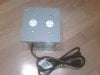
Put the cover on and your done!
How to Build a Four Light Grow Light Controller for Less Than $80
Anyone that has more than two 1000 watt lights in their home has probably run into the problem of how to supply power and turn them on and off. A standard 120 volt circuit in your home has a 15 amp rating, that means one light. Note: I will be using the term "120 volt" and "240 volt" to describe the two different types of circuits we will be working with only because that's the term the ballast manufactures use. They are often referred to as "110 volt" or "220 volt", actually if you measured the voltage with an accurate meter a 120 volt circuit often will be less than that an can vary. A 1000 watt light draws about 9.2 amps at 120 volts (1100 watts / 120 volts = 9.17 amps). On a 240 volt circuit the amperage is 4.6 amps (1100 watts / 240 volts = 4.58 amps), so when running multiple light systems, it's easier to wire them for 240 because you can use smaller wire.
In a 120 volt circuit, the power cords have three wires; a black, a white and a green. The black is the "power" or 120 volts, the white is the "common" or "return" and the green is the ground. In a three wire 240 volt circuit, like we use for grow lights, there is also a black, white and green. The black and white are both 120 volts (180 degrees out of phase with each other) and the green is the common and ground. In a 240 circuit we are splitting the load between two wires.
The problem for most of you is that you just can't go out and buy a timer that you can "plug in" four lights. I have looked at many different lighting controllers for the hydroponics industry and found that most are $200 to $300 for what amounts to a $30 relay in a box with some outlets. I know many of you like to build this stuff on your own, so I setout to build one of these with safety and low price in mind and to get as much of it from Home Depot as I could. I know that some of you have built controllers based on the Intermatic T103 timers they will work for four lights but what do you do when you have eight or twelve lights and you want them to turn on at the same time? The answer is a relay.
A relay works like a light switch, it connects and disconnects two wires. The difference is that instead of flipping the switch with your finger, a relay has a coil that when power is applied, it makes the connection. The advantage of this is that the coil requires only minimal current. The one I am using draws 85 milliamps. That means I can control quite a few of these relays with one 15 amp timer. 15 amps / .085 (85 milliamps) = 176, or 176 four light controllers. I don't know if anyone has 704, 1000 watt lights, but if you did you could turn them all on with a $10 Home Depot timer! One problem though, you still need 176 different 30 amp circuits..... On with the project.
Warning: Electricity will kill you, it does not care if you cry "uncle", you could be barbecued in no time. If you don't understand how this works, don't do it.
What you need
Tools:
- A drill
- 3/16 drill bit
- Screw Drivers
- Wire Stripper, with Crimper
- Pliers
Prices from 8/7/03 6 x 6 x 4 Junction box $10.75
 4 connectors, 20A 250V,
NEMA 6-20 style $21.00
 4 feet of 14/3 SJO wire, more if you want to have the ballasts far from the power source. $2.32
  pack of at lease 3, 8-32 x 1 inch machine screws and nuts $0.78
  at least 15 ring terminals, 16 - 14 gauge wire, 8 - 10 stud. $2.55
  Dryer cord, 3 wire, 10 gauge $8.29
  16/3 power cord, 18/3 will work too $2.98
  5, "Romex Clamps" or Cord Restraints $0.99
 30 Amp Power Relay $19.95
  How it Works
When power is applied to the small black cord (the relay coil) the power from the dryer cord goes to the four yellow connectors. You will also need a dryer outlet.
Here is the relay. The power from the dryer cord is connected to the "LINE" side and the power to the grow lights goes on the "LOAD" side. The "COIL" is the trigger.
Here you can see the contacts. They will be pulled down by the electromagnet the coil charges.
This is a "double pole" relay. We will put one of our 120 volt wires on pole 1 and the other on pole 2. In a 240 volt circuit you must disconnect both 120 volt wires at the same time.
Here I have connected the 16/3 power cord to the coil to using the black and white wires. It does not matter what side you connect them to. When you plug it in you should hear a click and see the contacts close.
Just to give you an overview of how it works, here is the power coming in on the line side. Notice that the two outside wires on the dryer cord go to the two poles and the inner one is the ground. The black and white from the connector go to the load side of the two poles. In this situation, it does not matter what pole you connect the black or white to.
Assembly
First I put the relay in the center of the junction box and made some marks through the mounting holes of the relay. Then drilled two 3/16 inch holes.
I also drilled a hole in the side for the ground screw. Also above you can see the knock-outs missing. The one on the left is for the 16/3 power cord, this hole should measure 7/8 inch. The one on the left is for the dryer cord, it should measure 1-1/8 inch.
I prepared four sets of wires as shown above using the ring terminals. I made them one foot long but they can be longer if you have your ballasts far from the dryer plug. Since we are using 14/3 wire, you could make them long enough to go from one side of your house to the other. Be careful not to cut too deep into the insulation or you will cut the copper. Inside the yellow connector is a strip gauge for the wire (above left). If you cut too much of the black insulation off, the clamp will not hold.
When you crimp the ring terminals, test them. If you pull on them, they should not come apart!
Insert the wires into the connectors. The green must go to the green screw. Again, in this situation it does not matter where you put the black and white.
Assemble the rest of the connectors.
You should have with four sets of these.
After I mounted the relay, I connected the 16/3 power cord to the coil and the ground screw. If your using Romex clamps, put the clamp on first.
Then I connected the dryer cord to one side of the relay and grounded the center wire.
The hole on the left is 7/8 inch, the one on the right is 1-1/8 inch. The dryer cord comes with these funky clamps, you may have to bend it to get it through the hole.
Now it starts to get tight. I put the four 14/3 cords with the connectors through the box. The holes for these should be 7/8 inch. Notice the four black on one pole and the white on the other. Also they are all grounded. Now tighten all the screws and pack the wire against the inside of the box so nothing is rubbing the relay.
Use the cord restraints or Romex clamps to hold the wires in place. We have a special tool but pliers will work too.
Put the cover on and your done!