I have the Watts P60 2 port model, mine isn't working very well, it works OK on the low end (0-40PSI) then it stays at 40PSI until about 75-80PSI. It's erratic above there as well. Using one of the ports to mount a gauge is a good idea. Hope you have better luck.r0m- you got the same pressure reducer as me, right? I hope to not have issues with it. I looked over Cavadge's thread last week and noticed he used the same one! For some reason I thought he used a brass one, but nope- it's the same... Mine has 4 ports- and I like it cuz I mounted a gauge right on the top port...
Room30's HP Aero Cabinet
- Thread starter r0m30
- Start date
Trichy Bastard
Well-Known Member
OK- I'll let ya know if they suck in general, or if you just got a bad one... I really hope it works- it was hard finding a decent one that wasn't brass..I have the Watts P60 2 port model, mine isn't working very well, it works OK on the low end (0-40PSI) then it stays at 40PSI until about 75-80PSI. It's erratic above there as well. Using one of the ports to mount a gauge is a good idea. Hope you have better luck.
travish413
Well-Known Member
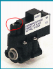
I have the pressure switch that came with my cdp 6800 and not sure if i can adjust it or if i can even use it? It has a sticker on the side showing "off" setting of 40 psi. I also have an ehcotech ccb-cs 12vdc that was in the box i had all of this stored away in, unfortunatly i cant find the owners manual so any help with which to use would be a great help. Im letting the paint dry on my veg cab as of right now and then gonna get started on my flower chamber. Im probably gonna need some plumbing help, so i hope yall dont mind. Thanks in advance for any help! Peace
If it's marked 40PSI then it is probably the PSW240. It's adjustable from 30 to 60PSI so the highest pressure you could run is 60-80PSI using that switch. The adjustment screw is on the top inside one of those two circular holes on the side away from the wire spades.
I don't know anything about the other switch you mention, have you tried to Google it?
I don't know anything about the other switch you mention, have you tried to Google it?
travish413
Well-Known Member
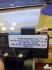 this is the switch that came with my pump.
  do you think this switch is adjustable? seems like a really small screw and no way of knowing how much to turn...
travish413
Well-Known Member
Cool! That allen head was so small i wasnt so sure about adjusting it. Thanks again for the help!Yes, that is a PSW240 so it is adjustable. You have to use a pressure gauge in the line when you adjust it to get it set correctly.
It's not a screw, you use an allen wrench.
rom in this pic why is your pressure regulator tied into the pressure switch? Im in the process of putting together my flower chamber and was going to run it: res,pump,filter,press switch,relief valve, acc, then cut in a T inbetween the relief valve and acc, add a pressure gauge,then run it to the presure regulator, add another gauge, solenoids, and mist heads. sound right?First off props to Cavadge on another forum for his inspiration and hard work documenting an HP Aero build, and thanks to all of the others who have been putting information about HP aero out there.
And now without further ado

The basics, starting at the top left you see a whisper fan with a DIY carbon block filter, these things are quiet! Thanks to Bulénath on ICMag for posting the DIY. Heres a better shot, just add carbon.

Top right: This is the electrical and the only place I could fit the accumulator. Its still a rats nest but Im not sure if Ill venture into power cord cutting just to make it pretty. The thing in the front that isnt very well in focus is my DIY recycle timer, its PIC based so it can be made to do just about any interval with software but Ill post a DIY when I get it a little more presentable. Right now its running at .05 seconds on/2 minutes off.

The rest of the left side is the flower chamber. It is a two bucket scrog setup. The buckets are a bucket-in-bucket design to create the root barrier.


HP Aero is usually drain to waste so behind the buckets is a condensate pump that pumps the waste water through the wall to the waste reservoir

Center Right: This is the clone and early veg section, this uses the same misters, pump and bucket design as the flower mist delivery system. The pump was ordered as a spare and rather than let it sit I put it to work driving the cloner. It probably isnt that much different than a LP cloner. This is all tied together with a PVC frame so the entire cloner can be removed as a unit for servicing.

Bottom right: These are my nutrient (top black tote) and waste water (lower black tote) reservoirs and against the far right wall is the Flower mist delivery system.

All of these can be taken out if the cabinet while it is still running for quick tweaks they can also be completely removed to do more elaborate maintenance.

Finally, a close up of the mist delivery system. The top ball valve allows for the removal of this piece without depressurizing the accumulator. The tube below that goes to a bulkhead in the wall that is attached to the solenoid and the misters. The bottom valve is to release the pressure in the system.
I still need to add a pressure relief valve as a third line of defense against failures that would over pressurize the accumulator

And Mr. Kill-a-watt says:

That's without the condensate pump or flower light. The condensate pump runs about 50 watts and the light I'm planning on buying is about 180 watts.
Trichy Bastard
Well-Known Member
From what I can see, the PS is just past the pump if I am thinking it is the part I see. Then the regulator is last in the line as it should be. This would be the correct configuration, only possible less than perfect scenario I see here is that the PS is remotely farther away from the accumulator than 24 inches, which is supposed to be the optimal max distance for the best pressure sensitivity according to the info Cavadge supplied when he called the custom accumulator company. However- I also think they imagined people would be using larger diameter copper pipe, so with the 1/4" jg line being so small I'd assume further distances are no biggie. The worst that would happen is the pressure switch would not trigger as precisely, but with a regulator, and pressure release valve, nothing other than imperfect pump cycles would occur and final misting would be unaffected.
Look closely at the last pic there's a T after the pressure regulator that goes into the pressure switch g? Why is that isn't the misreads suppose to go after the regulator?From what I can see, the PS is just past the pump if I am thinking it is the part I see. Then the regulator is last in the line as it should be. This would be the correct configuration, only possible less than perfect scenario I see here is that the PS is remotely farther away from the accumulator than 24 inches, which is supposed to be the optimal max distance for the best pressure sensitivity according to the info Cavadge supplied when he called the custom accumulator company. However- I also think they imagined people would be using larger diameter copper pipe, so with the 1/4" jg line being so small I'd assume further distances are no biggie. The worst that would happen is the pressure switch would not trigger as precisely, but with a regulator, and pressure release valve, nothing other than imperfect pump cycles would occur and final misting would be unaffected.
I thought TB explained it.
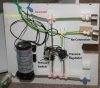
I've annotated the picture so you can see the pressure areas. The red line traces the high/unregulated pressure and the yellow line traces the low/regulated pressure. I think you might be getting confused because the regulated pressure line passes under the unregulated pressure line. I was working with the space I had so that's just how it ended up.
I've annotated the picture so you can see the pressure areas. The red line traces the high/unregulated pressure and the yellow line traces the low/regulated pressure. I think you might be getting confused because the regulated pressure line passes under the unregulated pressure line. I was working with the space I had so that's just how it ended up.
Trichy Bastard
Well-Known Member
Yeah, I'd assume it was that crossing he thought was actually a junction... What took me a couple stares was to figure out those things to the right are actually gauges from a profile view- I thought they were parts of solenoids or something at first haha...
Well Dickhead, does it all makes sense to you now?
Well Dickhead, does it all makes sense to you now?
Lol still not what dick head is talk aabout I was talking about where it goes pump T (to pressure switch) then it goes to another T( this is the one I'm referring to that goes to the pressure regulator). I thought the pressure regulator was suppose to get T into the line that goes after the pressure switch an then you regulate the pressure from the acc to the solenoids right? My set up is going to be like this correct me if I'm wrong: res,pump,pressure switch, pressure gauge, RV,acc, pressure regulator, solenoids, mist heads....
The pressure gauges are that way so I can see them when everything is in it's proper place. If you look at the closeup of the res and mist system in place the gauges are facing out and visible.Yeah, I'd assume it was that crossing he thought was actually a junction... What took me a couple stares was to figure out those things to the right are actually gauges from a profile view- I thought they were parts of solenoids or something at first haha...
Your sequence should work fine. My placement works too, you just have to think about it in terms of pressure zones. The Aquatec pressure switches are flow thru so the pressure everywhere in the "zone" I marked in red on the picture is at the pressure controlled by the switch.Lol still not what dick head is talk aabout I was talking about where it goes pump T (to pressure switch) then it goes to another T( this is the one I'm referring to that goes to the pressure regulator). I thought the pressure regulator was suppose to get T into the line that goes after the pressure switch an then you regulate the pressure from the acc to the solenoids right? My set up is going to be like this correct me if I'm wrong: res,pump,pressure switch, pressure gauge, RV,acc, pressure regulator, solenoids, mist heads....
If it's marked 40PSI then it is probably the PSW240. It's adjustable from 30 to 60PSI so the highest pressure you could run is 60-80PSI using that switch. The adjustment screw is on the top inside one of those two circular holes on the side away from the wire spades.
View attachment 1943714
I don't know anything about the other switch you mention, have you tried to Google it?
yes I understand that i just didnt understand your placement of the regulator I thought it would be T in on the the other side of the pressure switch thats all?The pressure gauges are that way so I can see them when everything is in it's proper place. If you look at the closeup of the res and mist system in place the gauges are facing out and visible.
Your sequence should work fine. My placement works too, you just have to think about it in terms of pressure zones. The Aquatec pressure switches are flow thru so the pressure everywhere in the "zone" I marked in red on the picture is at the pressure controlled by the switch.
Trichy Bastard
Well-Known Member
Dickhead- once you figure out how all this works, it seems painfully simple. However I remember how hard it was to grasp at first, before I had the tangible pieces in my hands. I think you are correct in your setup, so is r0m. The point of the pressure switch is that it does not have to be a specific point where water must flow through it first before then going somewhere else, it just needs to be inline somewhere on the unregulated side, hopefully as close to the accumulator as possible to get the most accurate readings as to which it is holding. Basically it will do it's job if installed anywhere on the unregulated side between the pump's output and the pressure regulator, but not recommended to be between the filter or anything that could obstruct pressure between it and the accumulator. (Probably the best placement is between the pump/filter and the accumulator: Pump>Filter>Pressure switch> accumulator>Regulator). Hopefully this explains better? I not mention again and I will help you un the specific point which you still don't understand.
EDIT: The pressure switch cannot be downstream from the regulator, otherwise the pressure switch will never sense the full pressure of the pump, only the regulated side and you will blow up that accumulator and your room to kingdom come- make sure you fully understand this before you literally kill yourself.")
This is the one "dangerous" aspect in dealing with compressed air in the tank at these pressures, however once setup properly, I would not hesistate to sleep inches from the whole setup unless the accumulator starts showing signs of rust or is overpressured past it's rated pressure.
EDIT: The pressure switch cannot be downstream from the regulator, otherwise the pressure switch will never sense the full pressure of the pump, only the regulated side and you will blow up that accumulator and your room to kingdom come- make sure you fully understand this before you literally kill yourself.
This is the one "dangerous" aspect in dealing with compressed air in the tank at these pressures, however once setup properly, I would not hesistate to sleep inches from the whole setup unless the accumulator starts showing signs of rust or is overpressured past it's rated pressure.
thanks tb Im still waiting for my press switch and reg so as soon as i get them ill put them together as u described! I have the same acc as you is it ok to lay on its side? thanksDickhead- once you figure out how all this works, it seems painfully simple. However I remember how hard it was to grasp at first, before I had the tangible pieces in my hands. I think you are correct in your setup, so is r0m. The point of the pressure switch is that it does not have to be a specific point where water must flow through it first before then going somewhere else, it just needs to be inline somewhere on the unregulated side, hopefully as close to the accumulator as possible to get the most accurate readings as to which it is holding. Basically it will do it's job if installed anywhere on the unregulated side between the pump's output and the pressure regulator, but not recommended to be between the filter or anything that could obstruct pressure between it and the accumulator. (Probably the best placement is between the pump/filter and the accumulator: Pump>Filter>Pressure switch> accumulator>Regulator). Hopefully this explains better? I not mention again and I will help you un the specific point which you still don't understand.
EDIT: The pressure switch cannot be downstream from the regulator, otherwise the pressure switch will never sense the full pressure of the pump, only the regulated side and you will blow up that accumulator and your room to kingdom come- make sure you fully understand this before you literally kill yourself.
This is the one "dangerous" aspect in dealing with compressed air in the tank at these pressures, however once setup properly, I would not hesistate to sleep inches from the whole setup unless the accumulator starts showing signs of rust or is overpressured past it's rated pressure.
Trichy Bastard
Well-Known Member
Cool man, I recommend going over your final setup here with us before turning it on to be safe? Or at least stare hard at the pressure gauge and make sure it doesn't go over 150 on the unregulated side. Unfortunately the tank specifically states in the installation manual that it cannot be placed on it's side- but in most cases it's not a big deal. Do you think it will be a major issue for your space? Honestly this tank is nearly as tall as it is wide, so laying it down won't change much but a few inches either way. I bet you're excited to take it to the next level!thanks tb Im still waiting for my press switch and reg so as soon as i get them ill put them together as u described! I have the same acc as you is it ok to lay on its side? thanks
Hey man nice setup! I got a few of the same parts you use. I have 28 of those red misters from cloudtop, there all i run, and the 6800 pump, my grow room uses 3 of um. I even made my own LED arrays, but i have no solenoids, pressure regulators, or accumulator tanks,... although the toy lover in me's got me wondering what do they all do for you? Give you more pressure? I also made a 2 misters per 5Gal bucket system, currently have 10 misters running off a 6800 pump, 6sec on/7min off, and i hit 90psi, and root masses pretty much fill a bucket by time i chop one down. Not to sound snide, might be a dumb question on my part, but what do all those other gadgets do for you, vs not having them like i don't?

ThanksHey man nice setup!
Not more pressure, consistent pressure.I got a few of the same parts you use. I have 28 of those red misters from cloudtop, there all i run, and the 6800 pump, my grow room uses 3 of um. I even made my own LED arrays, but i have no solenoids, pressure regulators, or accumulator tanks,... although the toy lover in me's got me wondering what do they all do for you? Give you more pressure?
You don't sound snide, looking at a HP areo setup can give you that WTF feeling. The accumulator, pressure regulator and solenoids give you a consistent pressure at the nozzles so that they provide as much of the mist at the target size of ~50 microns as possible. Without those components your pressure and mist quality will vary during the time the pump takes to pressurize the lines when it starts up and again as the pressure falls off when the pump shuts off. I don't know exactly how much of an effect that has on your plant growth but if I'm going to do this I'm going to shoot for the best possible outcome.I also made a 2 misters per 5Gal bucket system, currently have 10 misters running off a 6800 pump, 6sec on/7min off, and i hit 90psi, and root masses pretty much fill a bucket by time i chop one down. Not to sound snide, might be a dumb question on my part, but what do all those other gadgets do for you, vs not having them like i don't?
Another benefit is that the pump runs very little compared to a setup like yours, most HP pumps are not designed for constant cycling although PF has run his Aquatec that way for quite a while without a failure.